English Deutsch Silent Lab / SPARK⁴ Assembly Manual Instructions by
silent lab
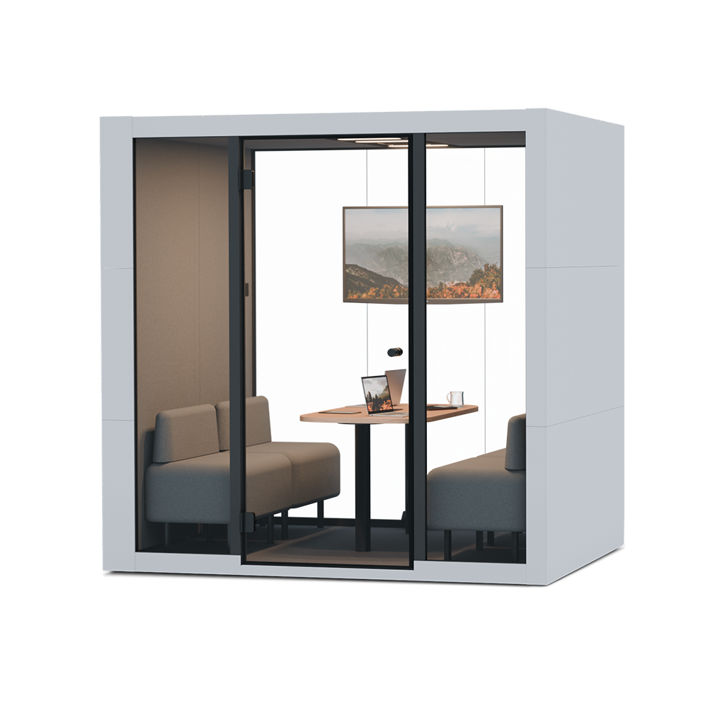
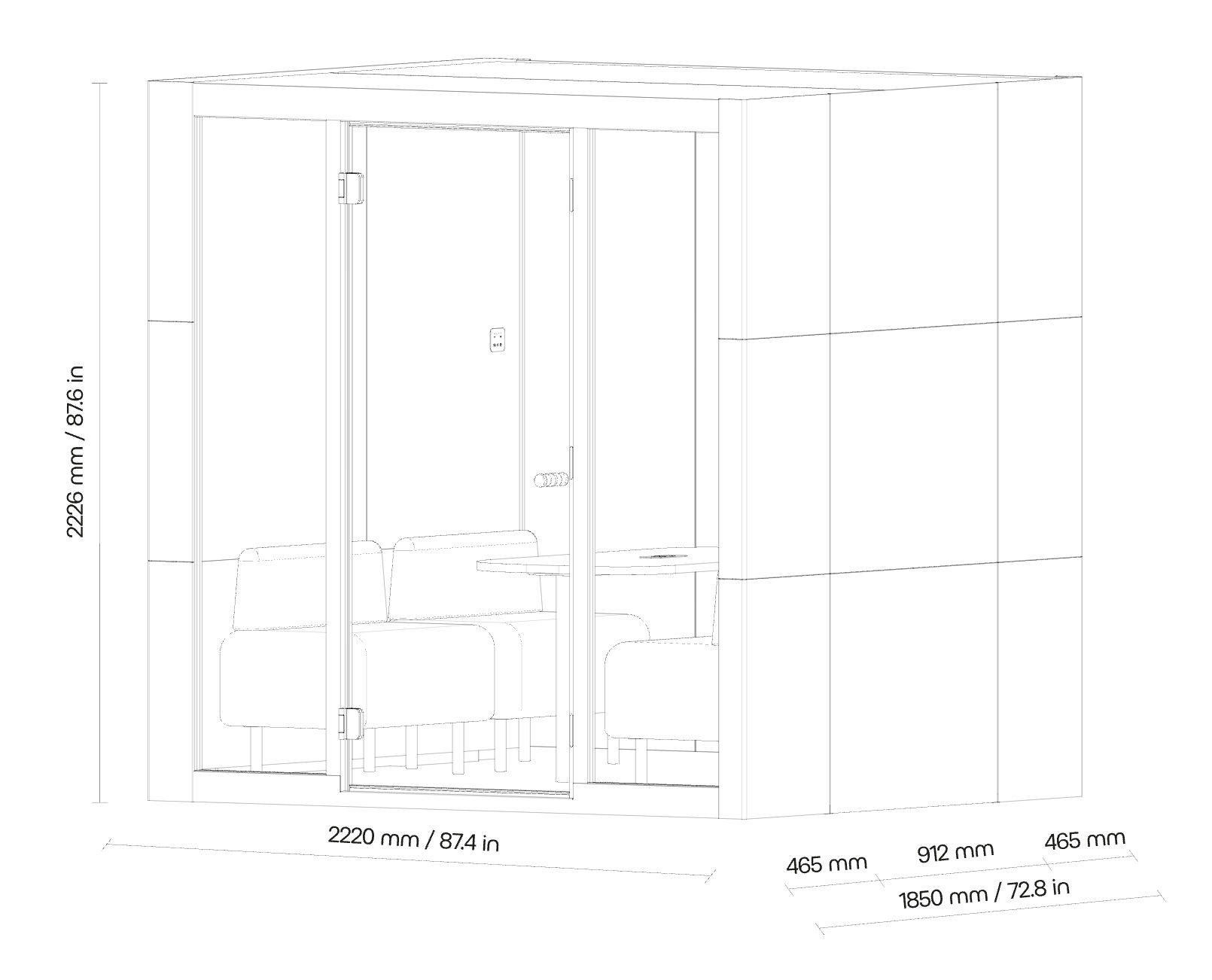
SPARK⁴ Assembly Manual Step-by-step guide for assembling the Spark 4 acoustic pod by SilentLab.
Preparation
1. Warning Ensure that the MICROOFFICE is not exposed to voltage during assembly. May result in irreparable damage or injury.
2. Screw tightening force For all metric screws, use a force of 13 Nm. For hinges, use a force of 15 Nm.
Floor
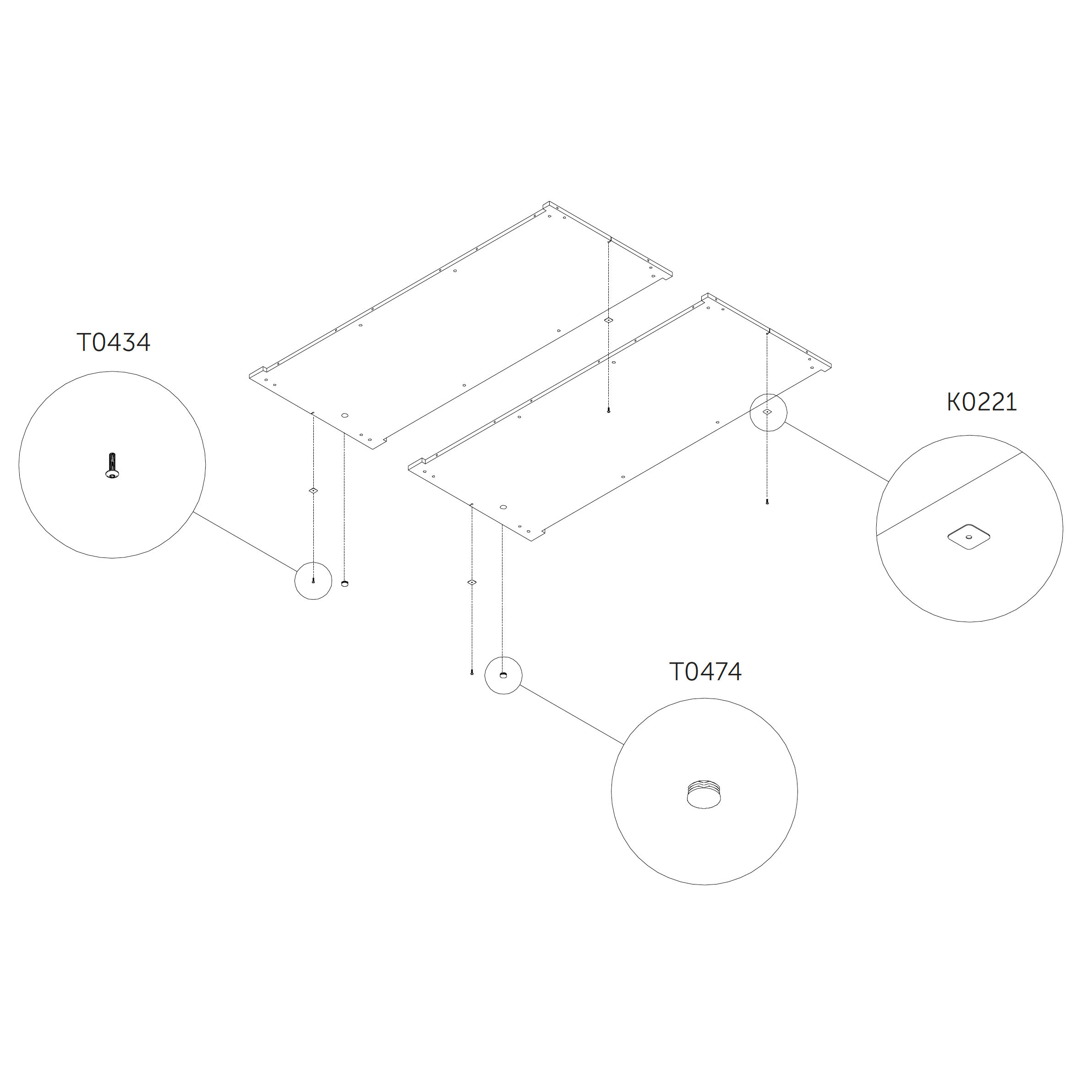
3. Attach washers to the floor panel
Place the washers into the designated recesses in both floor panels 1.0_S.
Secure each with a flanged button head screw.
Parts used:
M6×25 mm flanged button head | T0434 | 4×
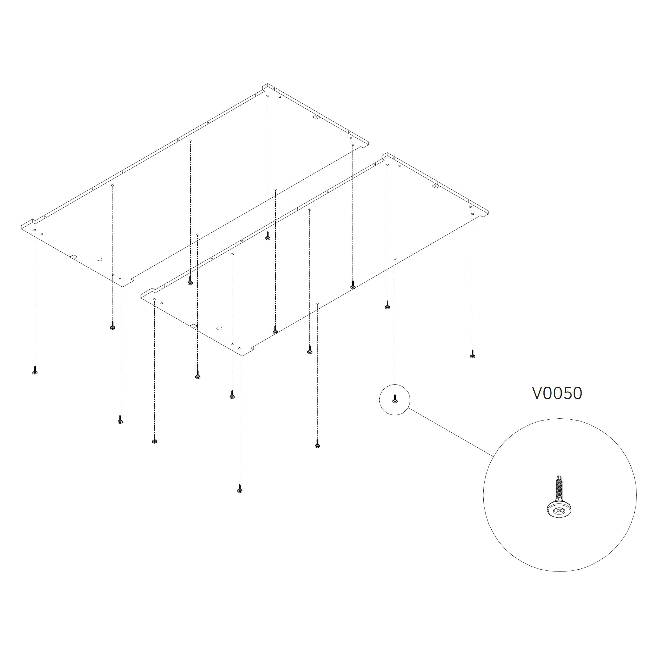
4. Install the standing feet
Screw the standing feet into the threaded inserts on the underside of the floor panels 1.0_S.
After leveling, ensure a minimum clearance of 20 mm between the floor and the ground.
Parts used:
standing foot | V0050 | 16×
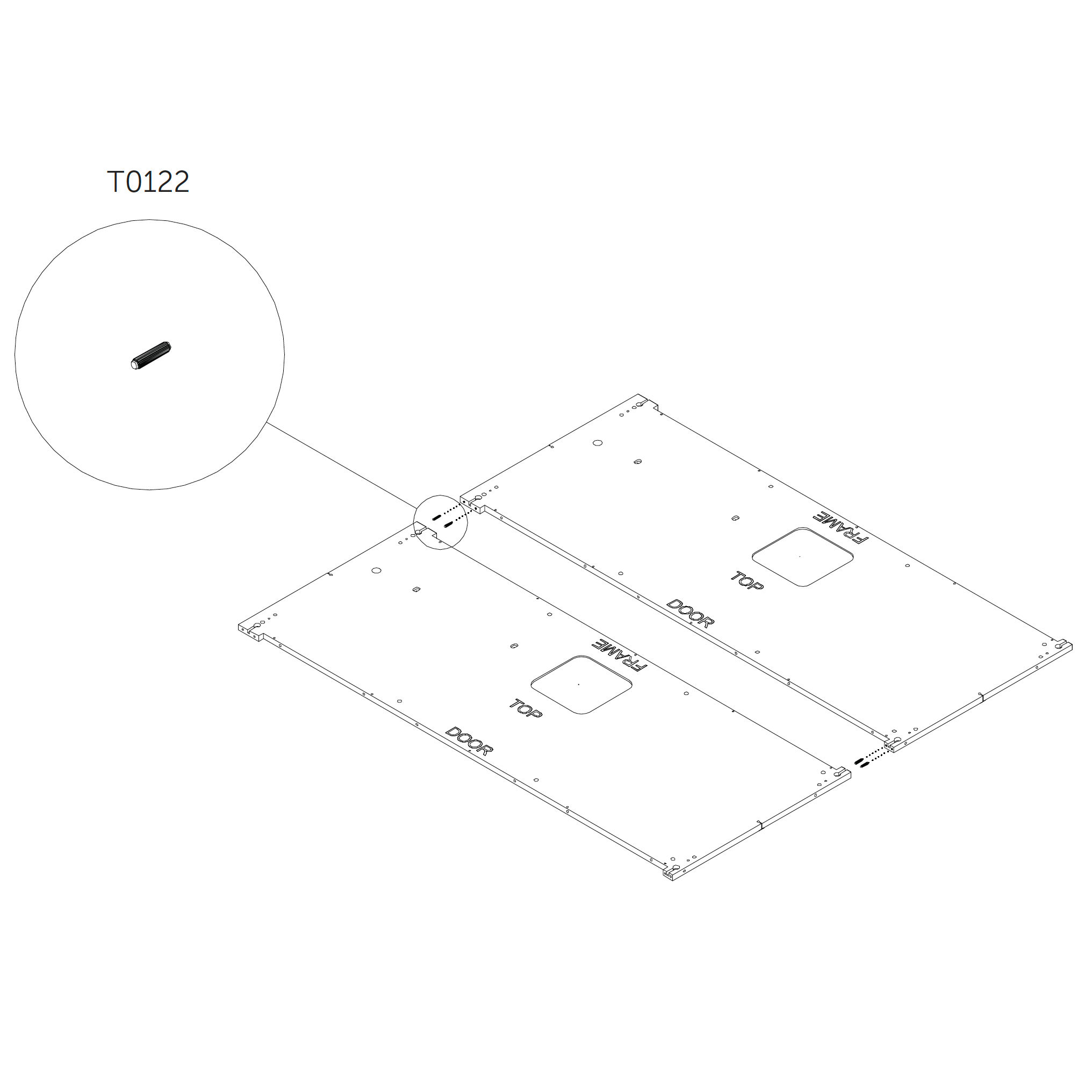
5. Join the floor panels
Join two parts 1.0_S by using zipbolts.
Place wooden coupler secure by using screws as shown.
Parts used:
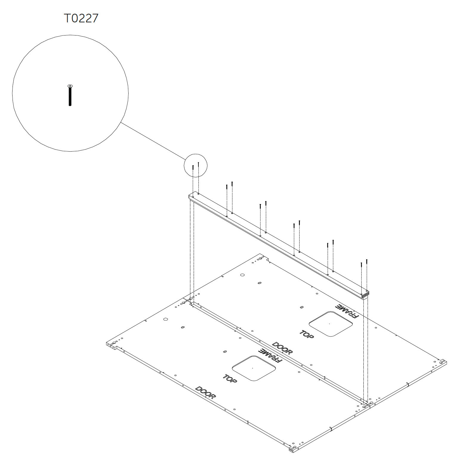
6. Secure the wooden coupler
Parts used:
M4×40 mm hex head metric screw | T0227 | 12×
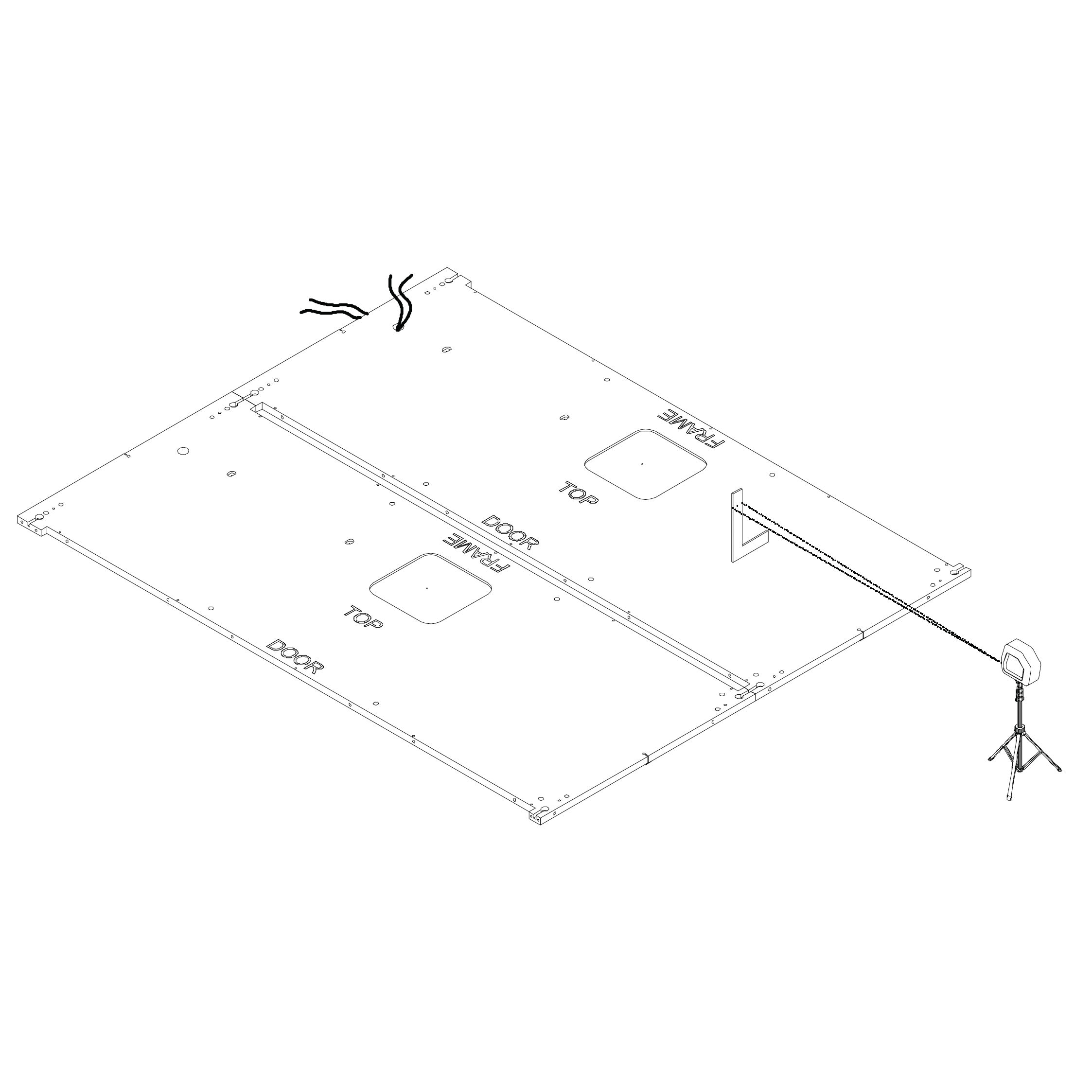
7. Insert the power source cable and level the floor
Pull the power source cable through the installation hole.
Use a laser level and L-square ruler to adjust the height of the standing feet and level the floor.
Once level, insert dowel pins into the predrilled holes.
Parts used:
Dock Panels
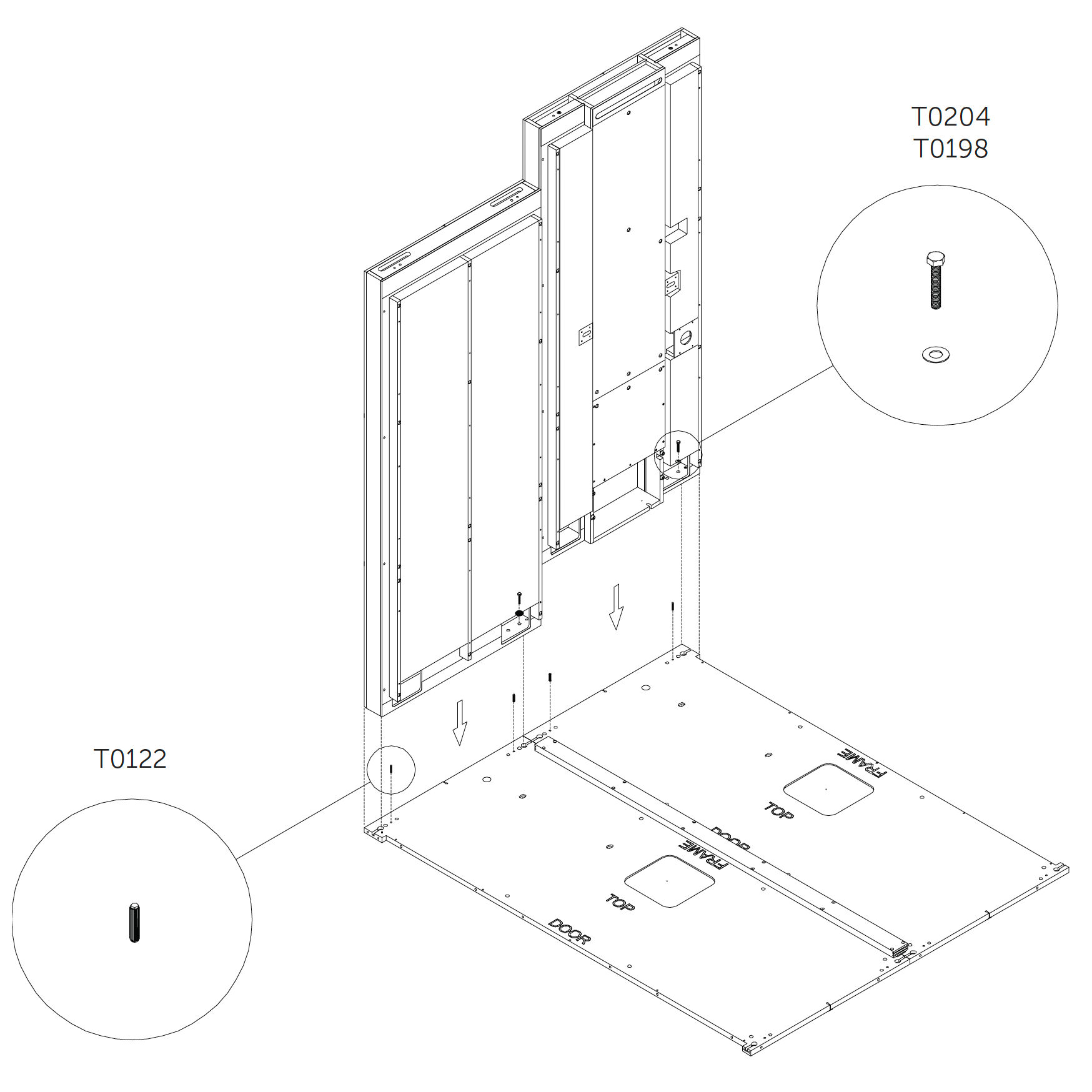
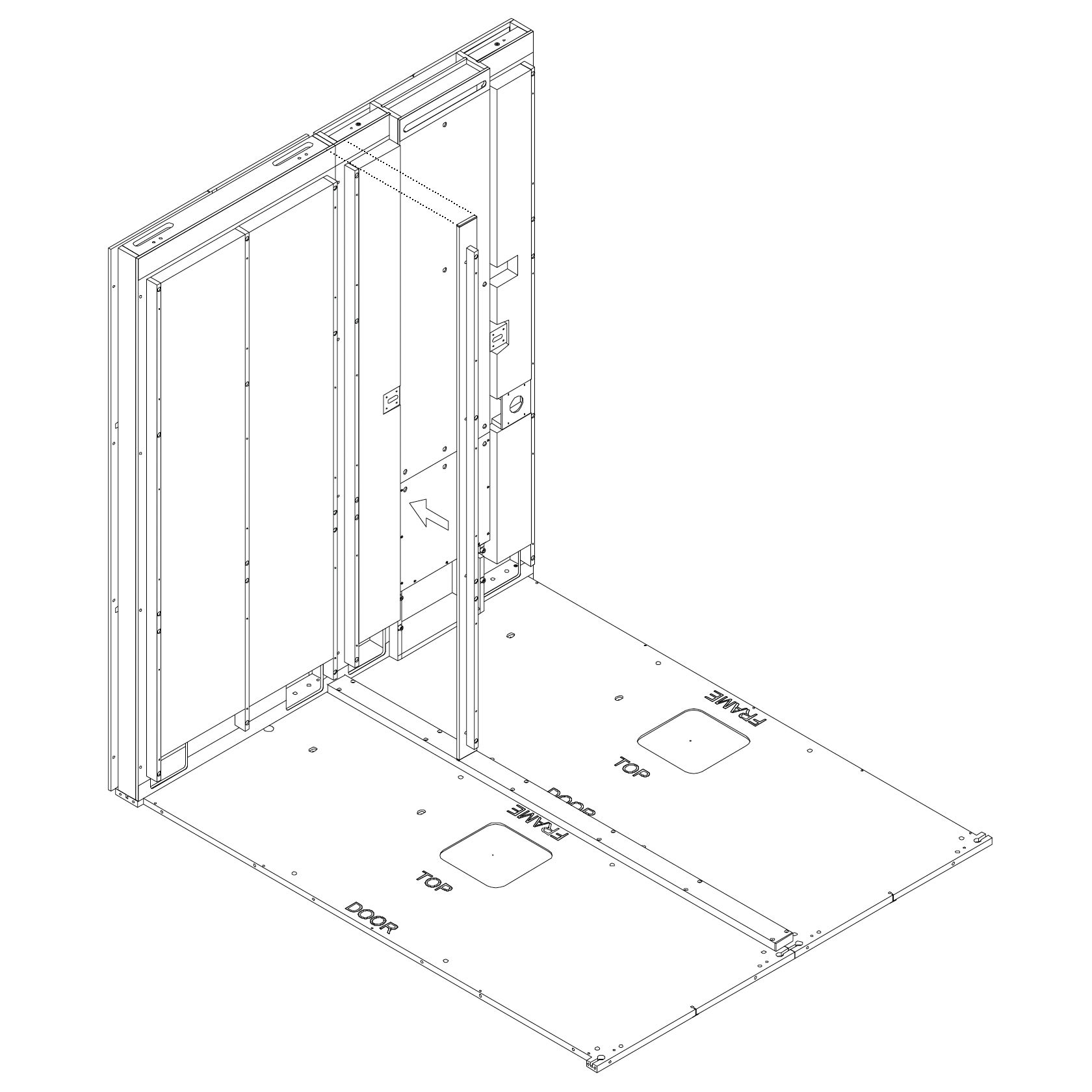
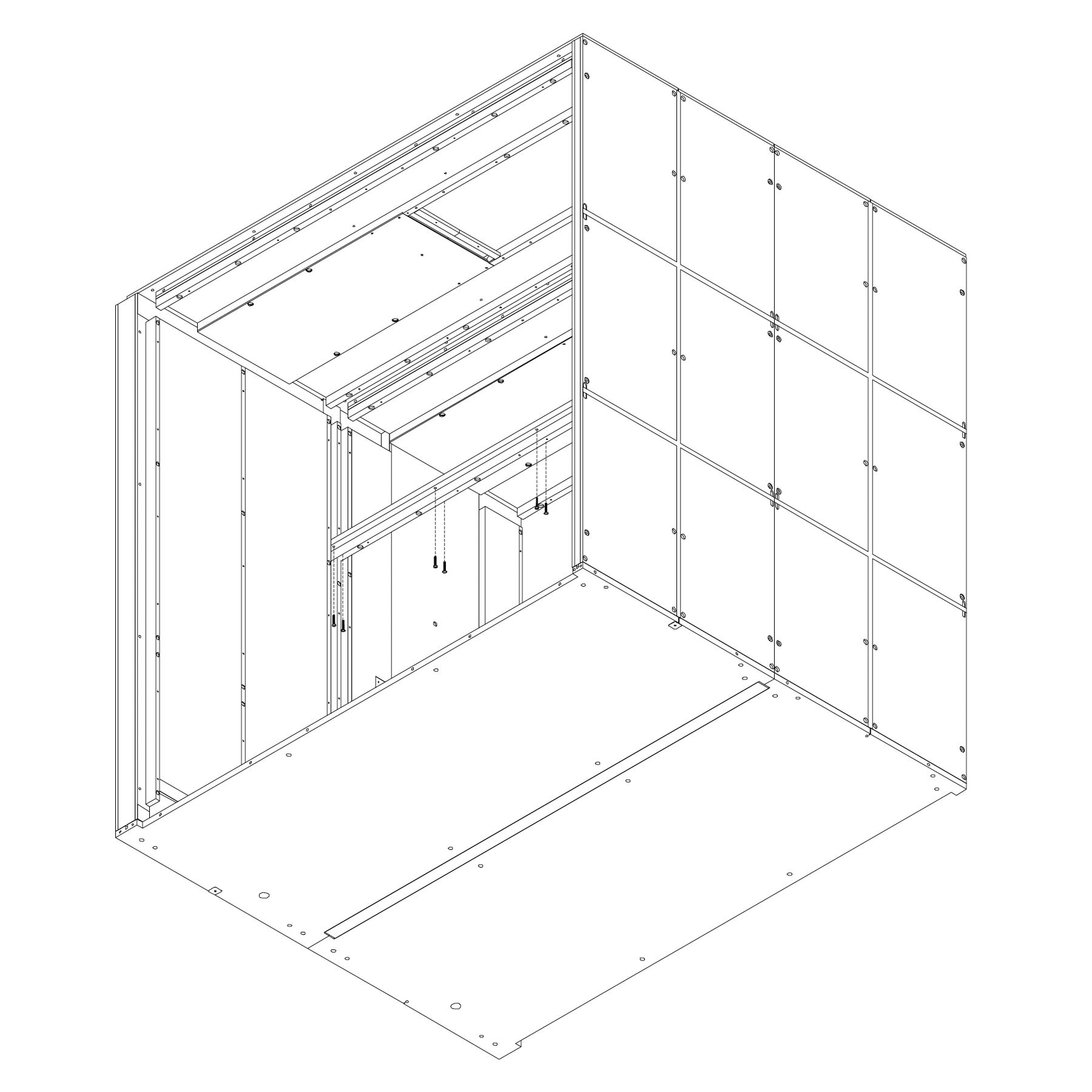
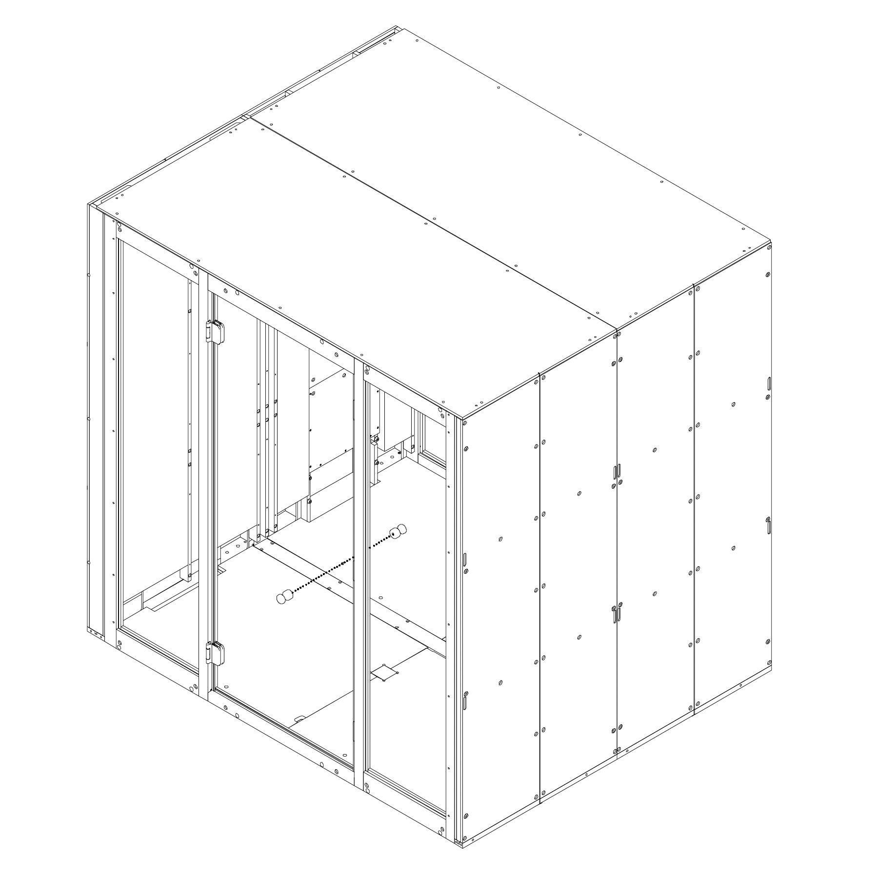
8. Position and secure the dock panels
Insert dowel pins into the floor panel.
Place the first dock panel (2.0_S) in position.
While positioning, pull the power cable through the dock and plug it into the circuit breaker connector.
Attach the dock panel using screws and washers. Do not tighten the screws yet.
Repeat for the second dock panel.
Parts used:
9. Attach the wooden coupler
Position the coupler across the top of the dock panels.
Fasten it using screws as shown.
Parts used:
M6×120 mm hex head metric screw | T0430 | 8×
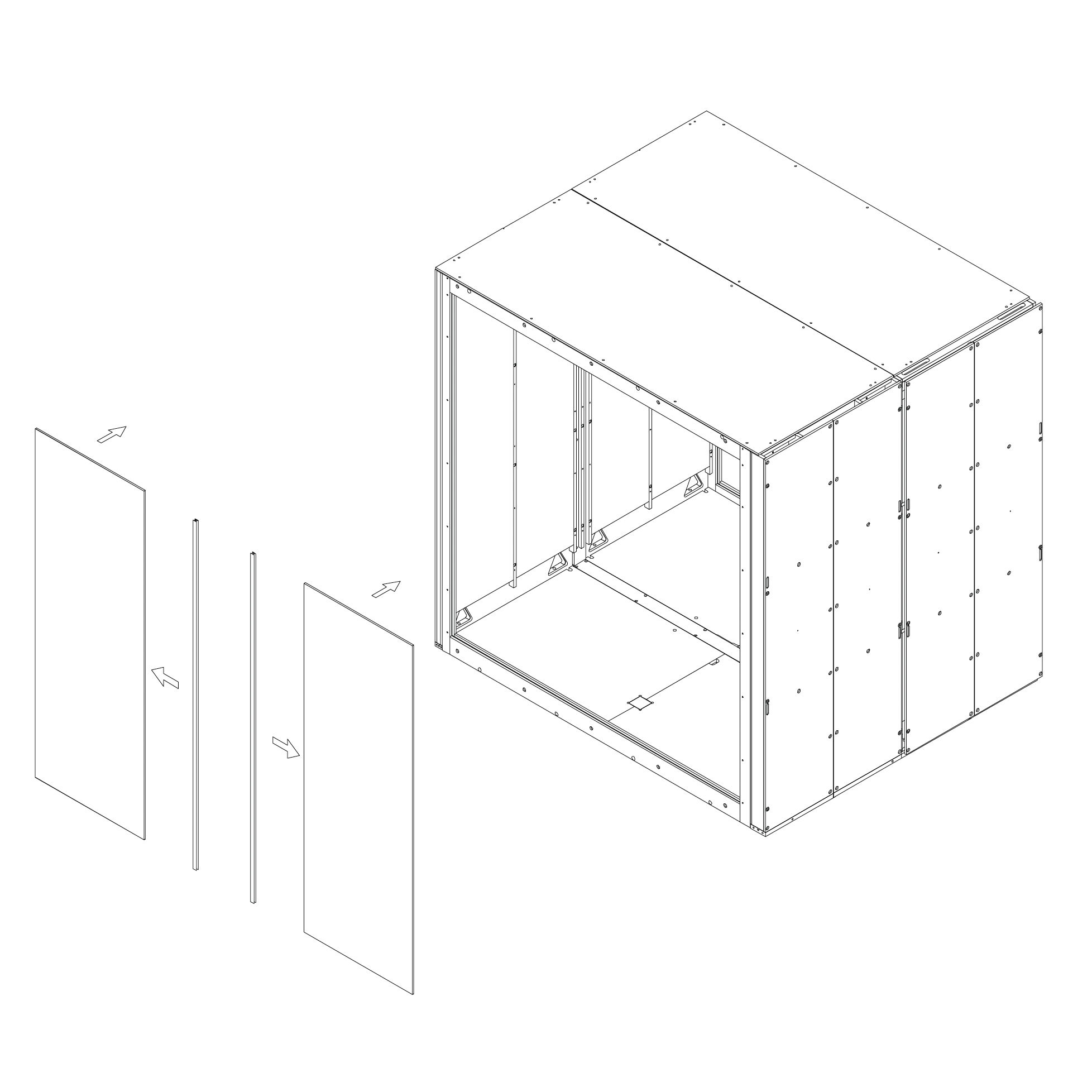
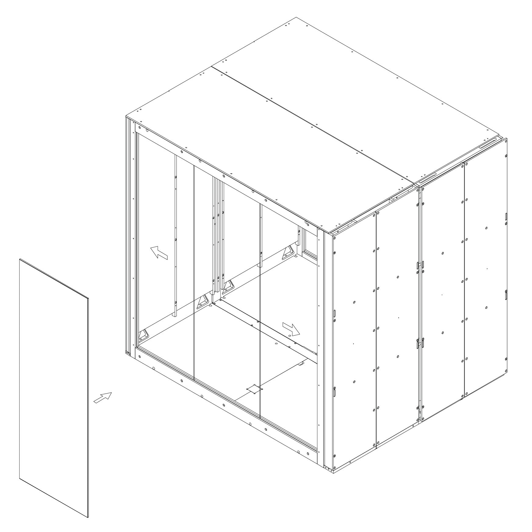
Wall Panel
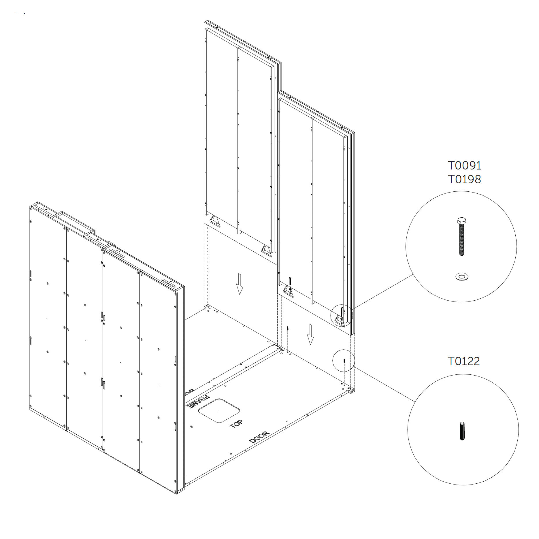
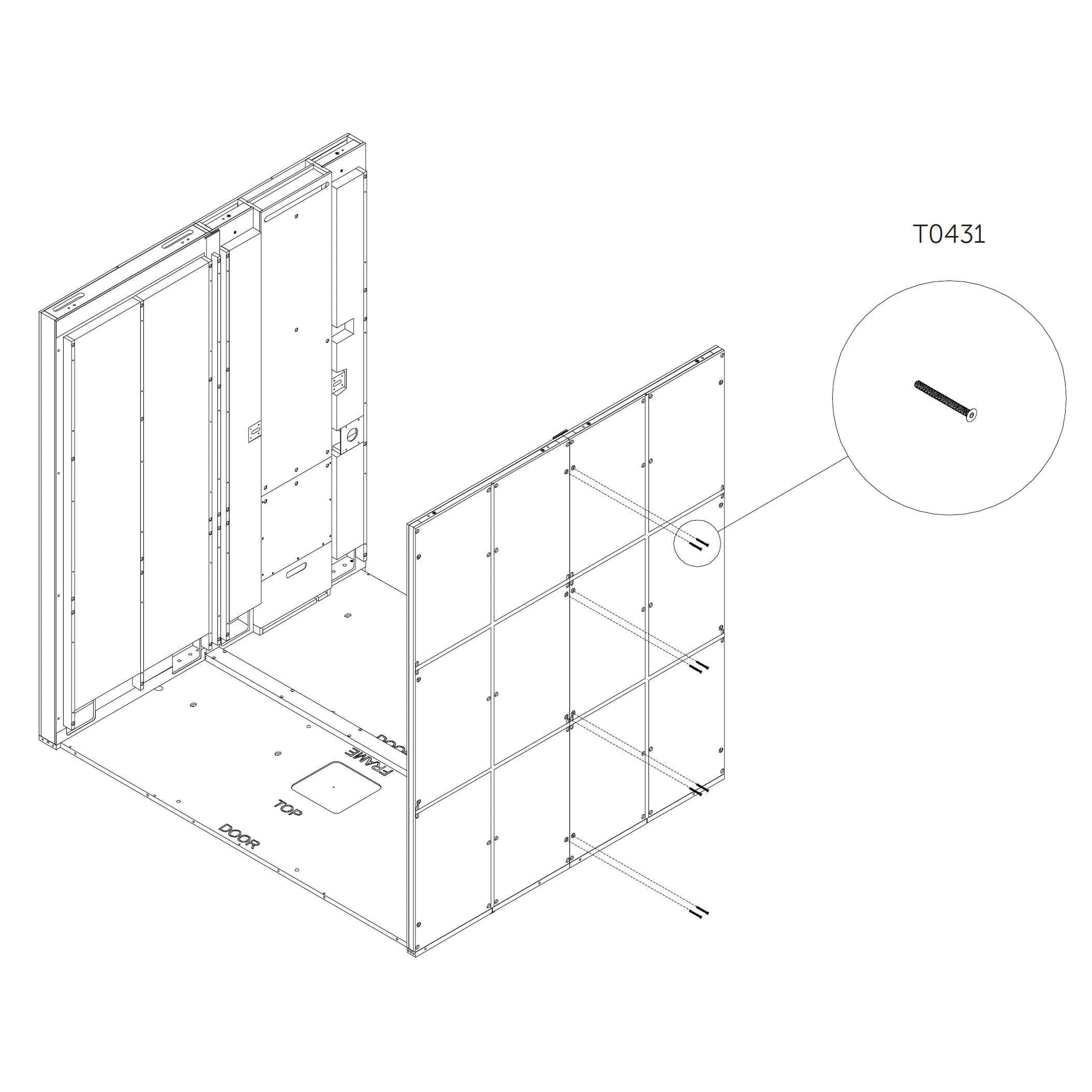
10. Position and secure the wall panel 3.0_S (wall panel)
Insert dowels into the floor panel.
Place the wall panel (3.0_S) in position.
Use screws and washers to fasten it to the floor panel.
Do not fully tighten the screws at this stage.
Parts used:
M8×70 mm hex head metric screw | T0091 | 4×
washer | T0198 | 4×
dowel pin | T0122 | 4×
M6×65 mm hex head metric screw | T0431 | 8×
11. Attach the second wooden coupler
Align the coupler as shown in the diagrams.
Fasten it securely using screws.
Parts used:
M6×120 mm hex head metric screw | T0430 | 8×
Roof Panel
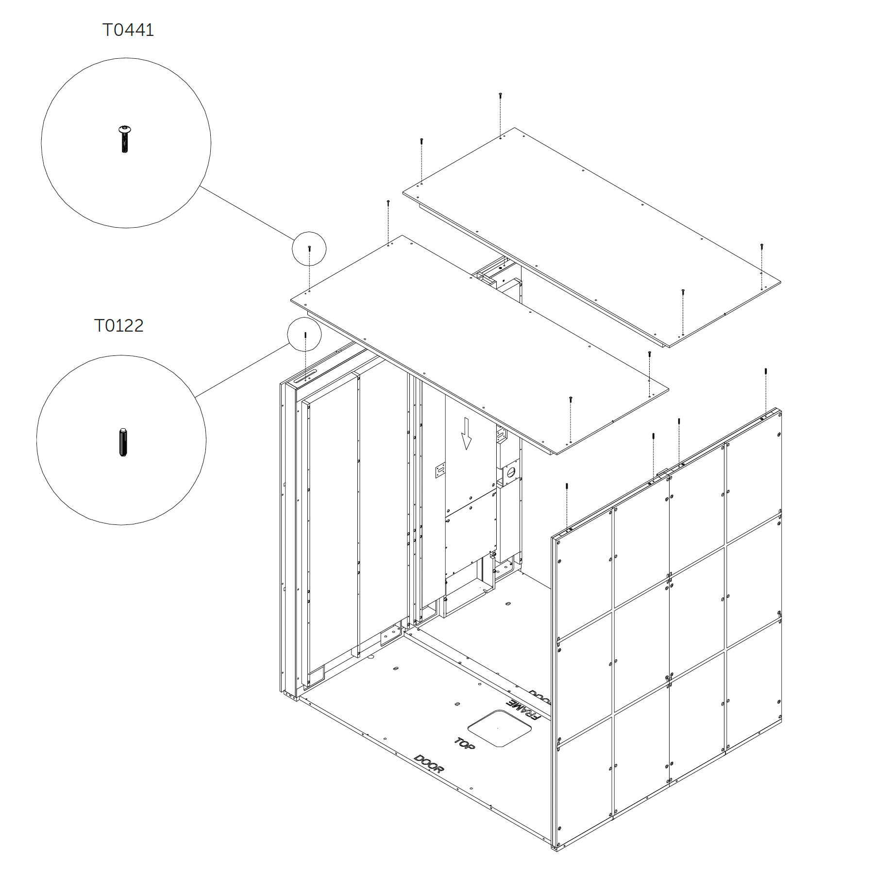
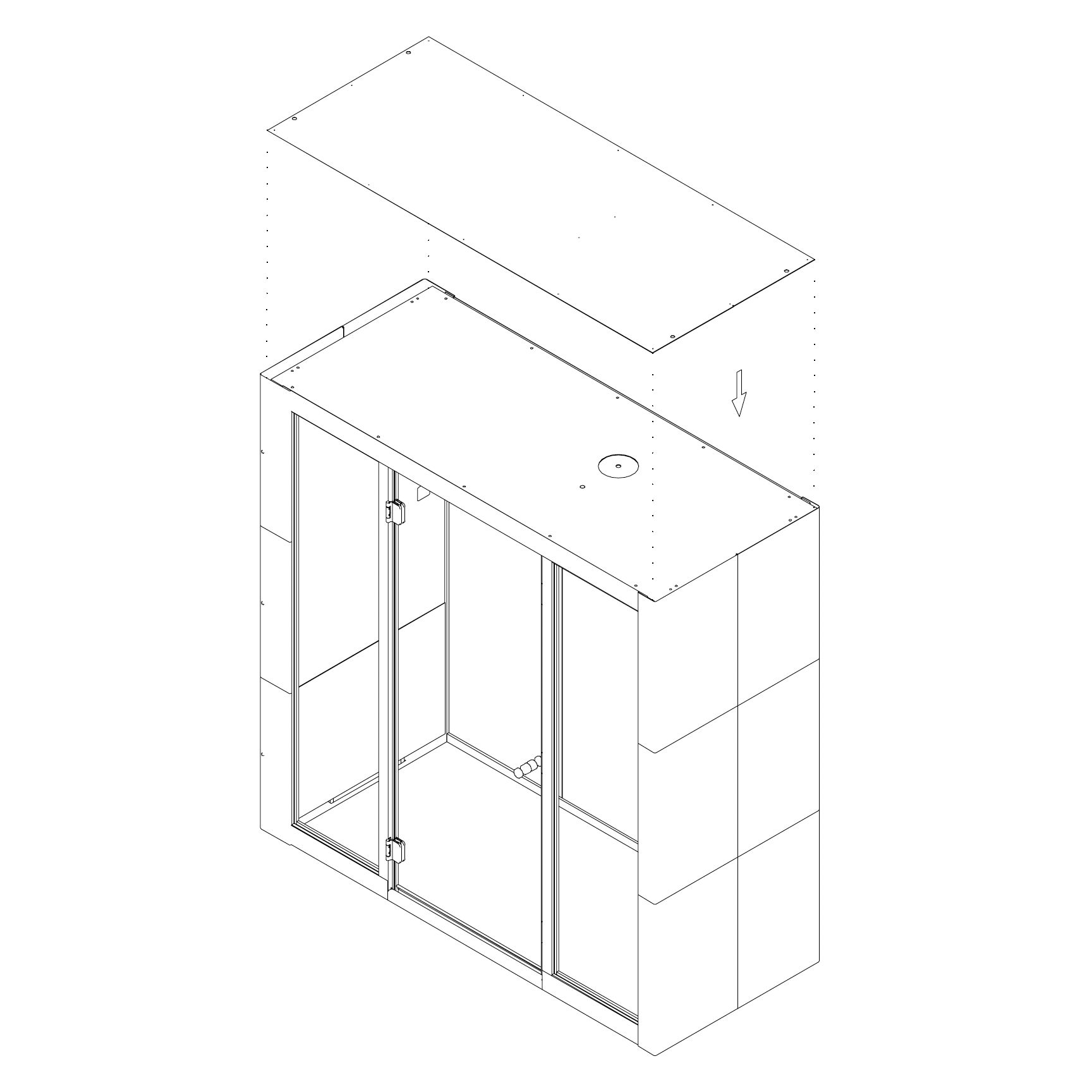
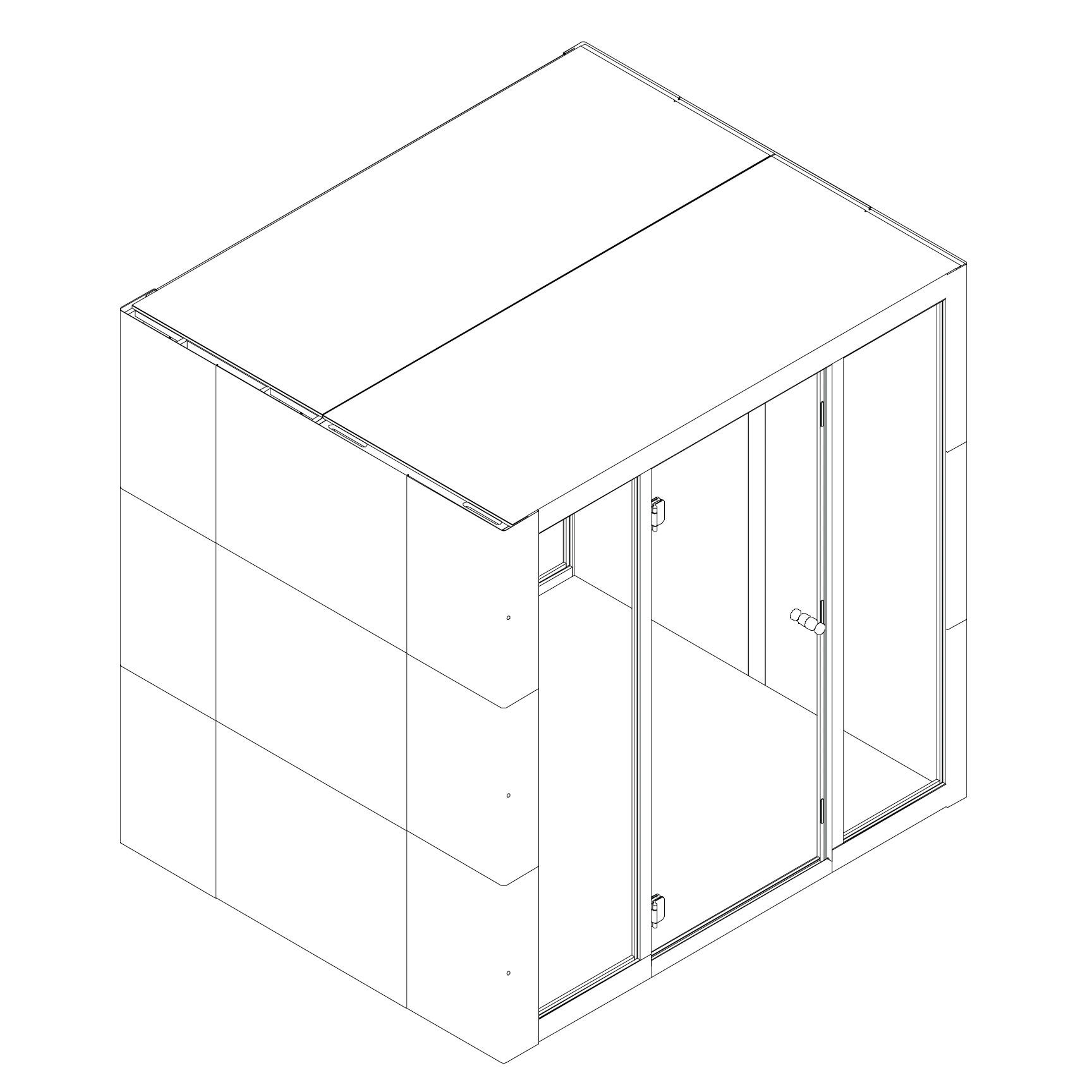
12. Position and fasten the roof panel 4.0_S² (roof panel)
Insert dowel pins into the predrilled holes in the top of the dock panel (2.0_S) and the wall panel (3.0_S).
Place the roof panel (4.0_S²) on top, aligning with the dowels.
Secure it from above using screws T0441.
Do not fully tighten the screws yet.
Parts used:
M8×70 mm hex head metric screw | T0441 | 8×
dowel pin | T0122 | 8×
M6×40 mm flanged button head screw | T0303 | 10×
13. Attach the last wooden coupler
Position the coupler as shown in the illustration.
Secure it using screws.
Parts used:
M6×65 mm hex head metric screw | T0431 | 8×
Rear Frame
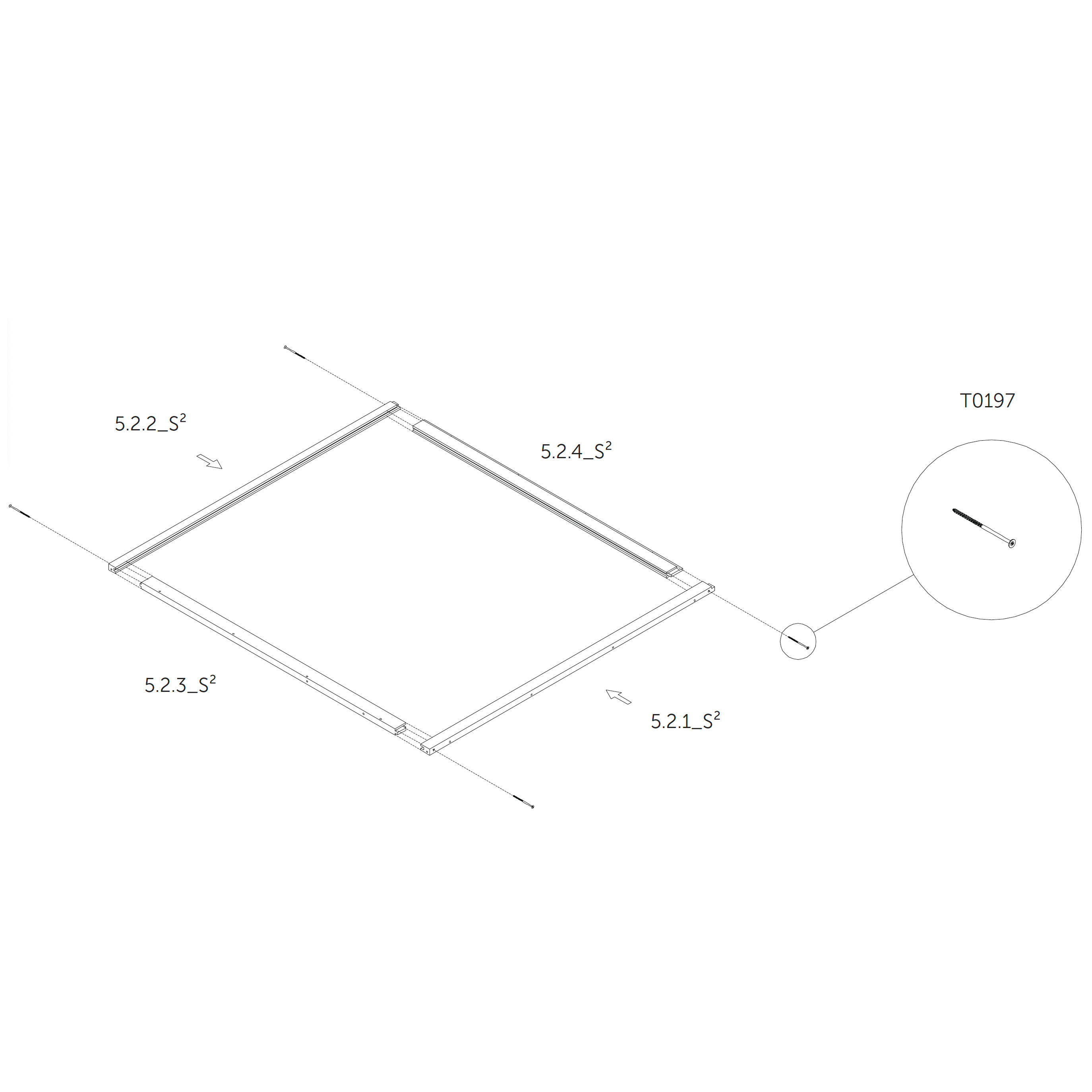
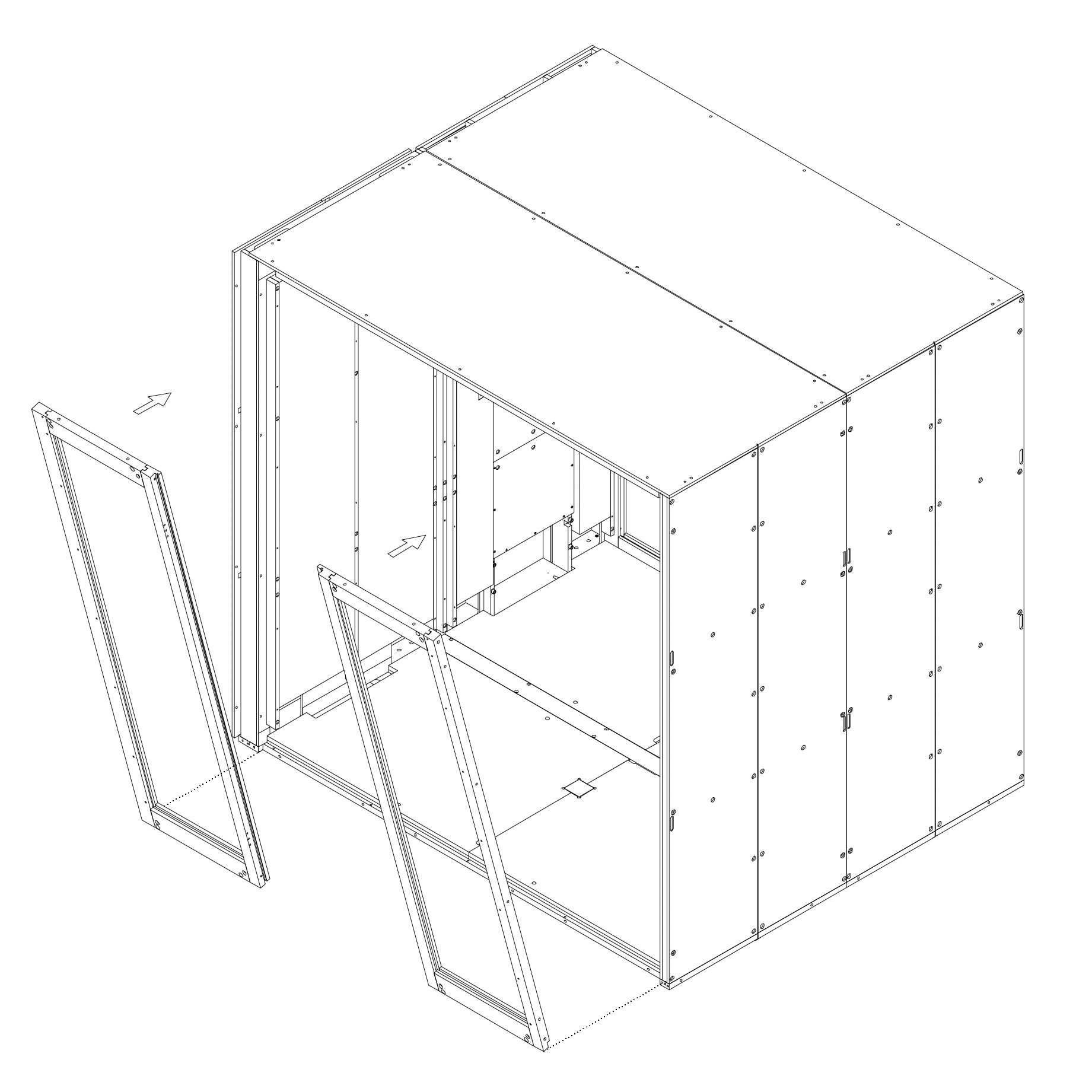
14. Assemble the frame 5.2.1_S², 5.2.2_S², 5.2.3_S², 5.2.4_S² (rear frame)
Join the individual frame parts 5.2.1_S², 5.2.2_S², 5.2.3_S², and 5.2.4_S² together as shown.
Secure the joints using screws.
Parts used:
wood screw 6×160 mm | T0197 | 4×
metric screw M6×120 | T0430 | 4×
metric screw M6×65 | T0431 | 4×
metric screw M6×40 | T0397 | 4×
metric screw M6×30 | T0432 | 4×
washer | T0438 | 8×
dowel pin | T0122 | 4×
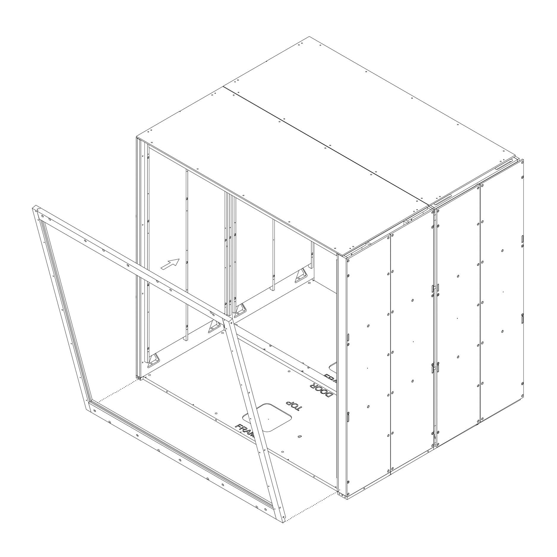
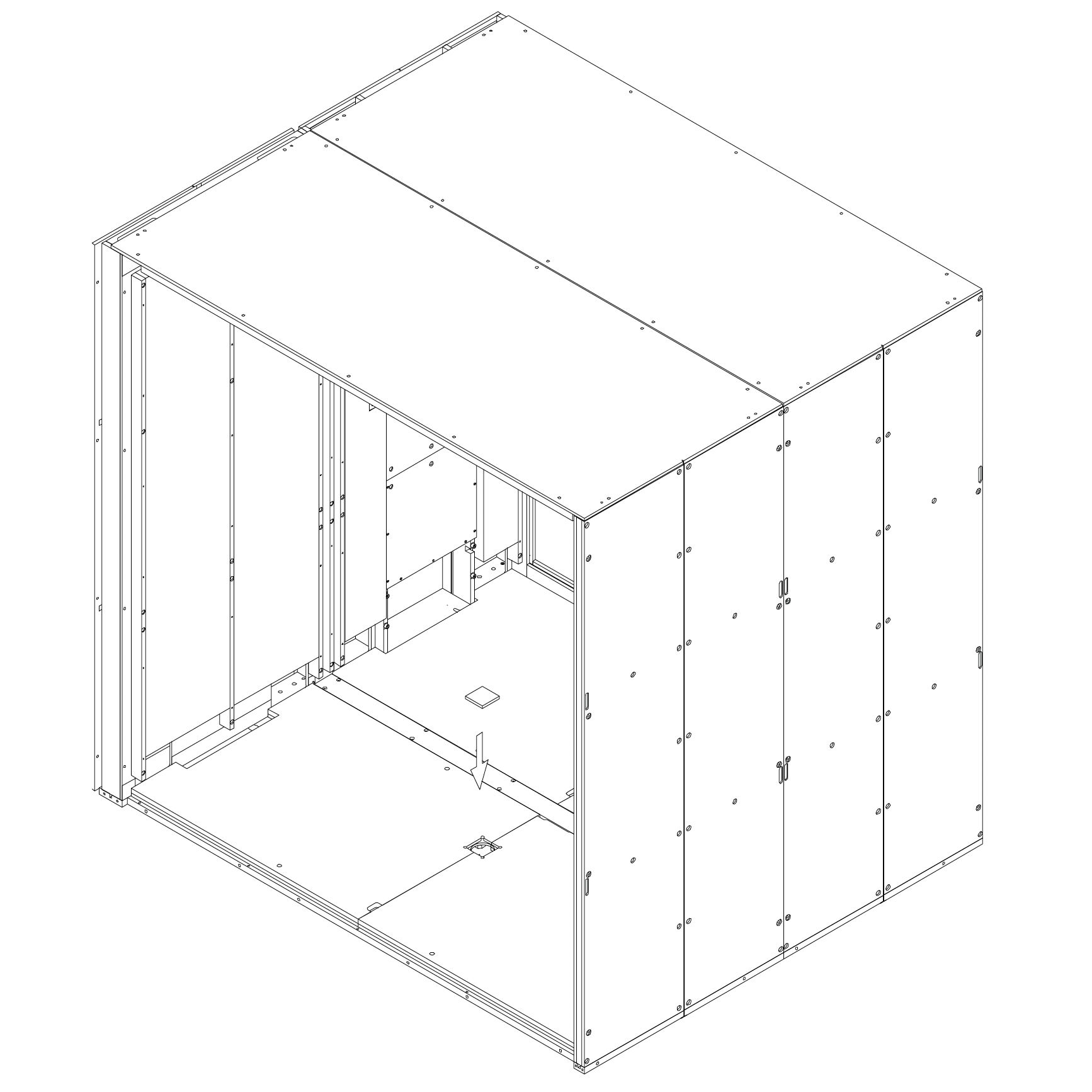
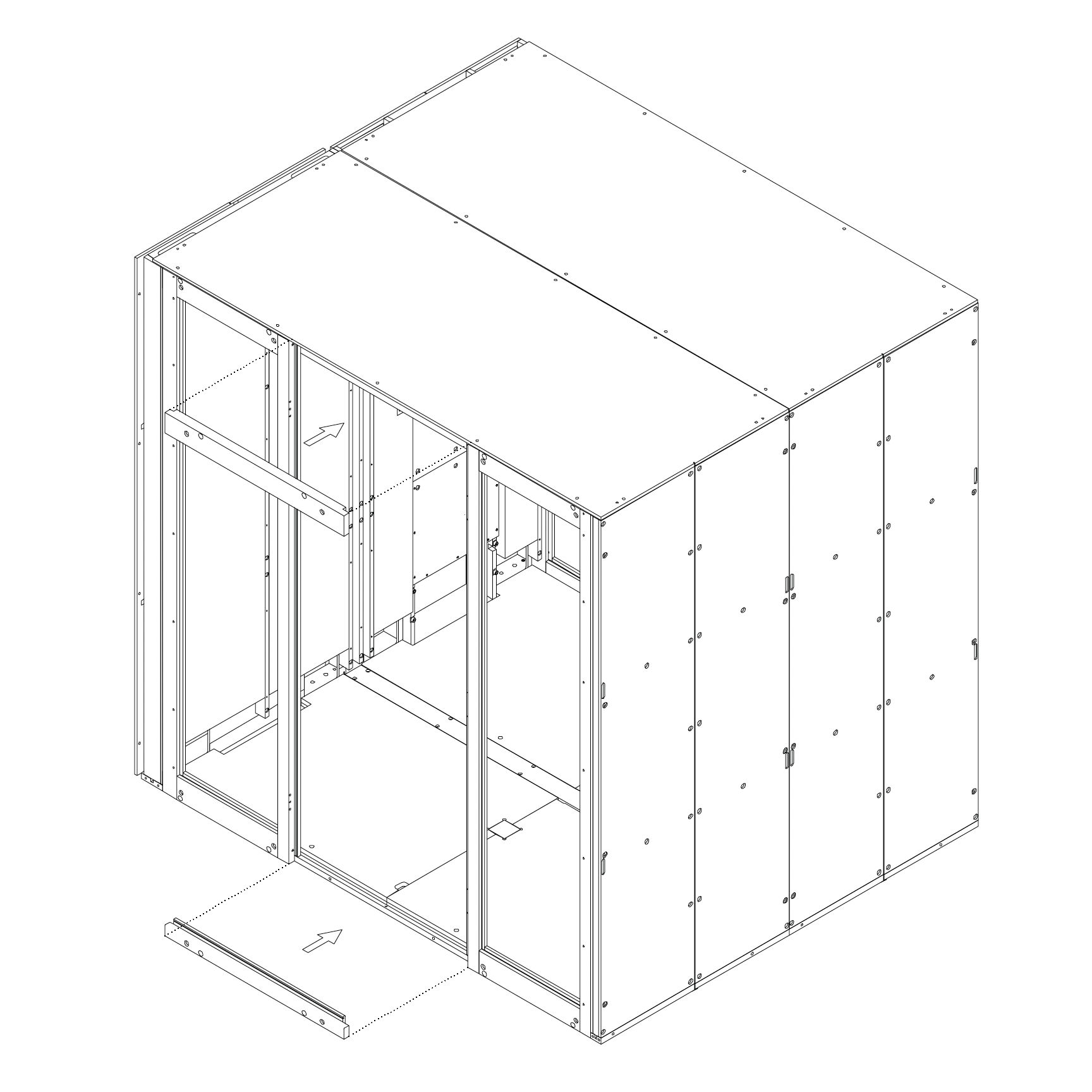
15. Install the frame
Position the fully assembled frame onto the structure.
Insert the lower section of the frame first, then the upper.
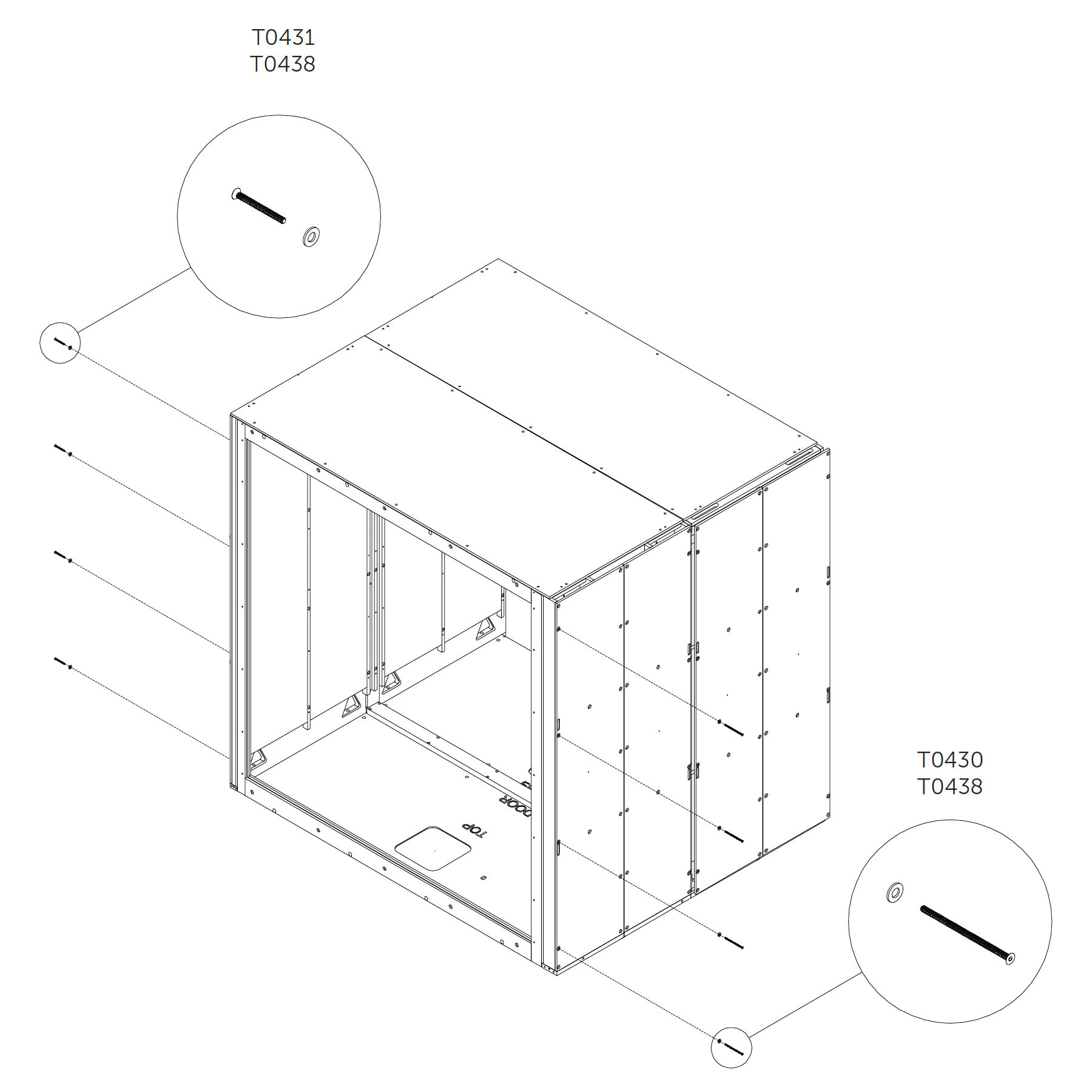
16. Secure the rear frame from the sides
Use screws and washers to fasten the frame from both left and right sides as shown.
Do not overtighten.
Parts used:
M6×65 mm hex head metric screw | T0431 | 2×
M6 washer | T0438 | 2×
M6×120 mm hex head metric screw | T0430 | 2×
M6 washer | T0438 | 2×
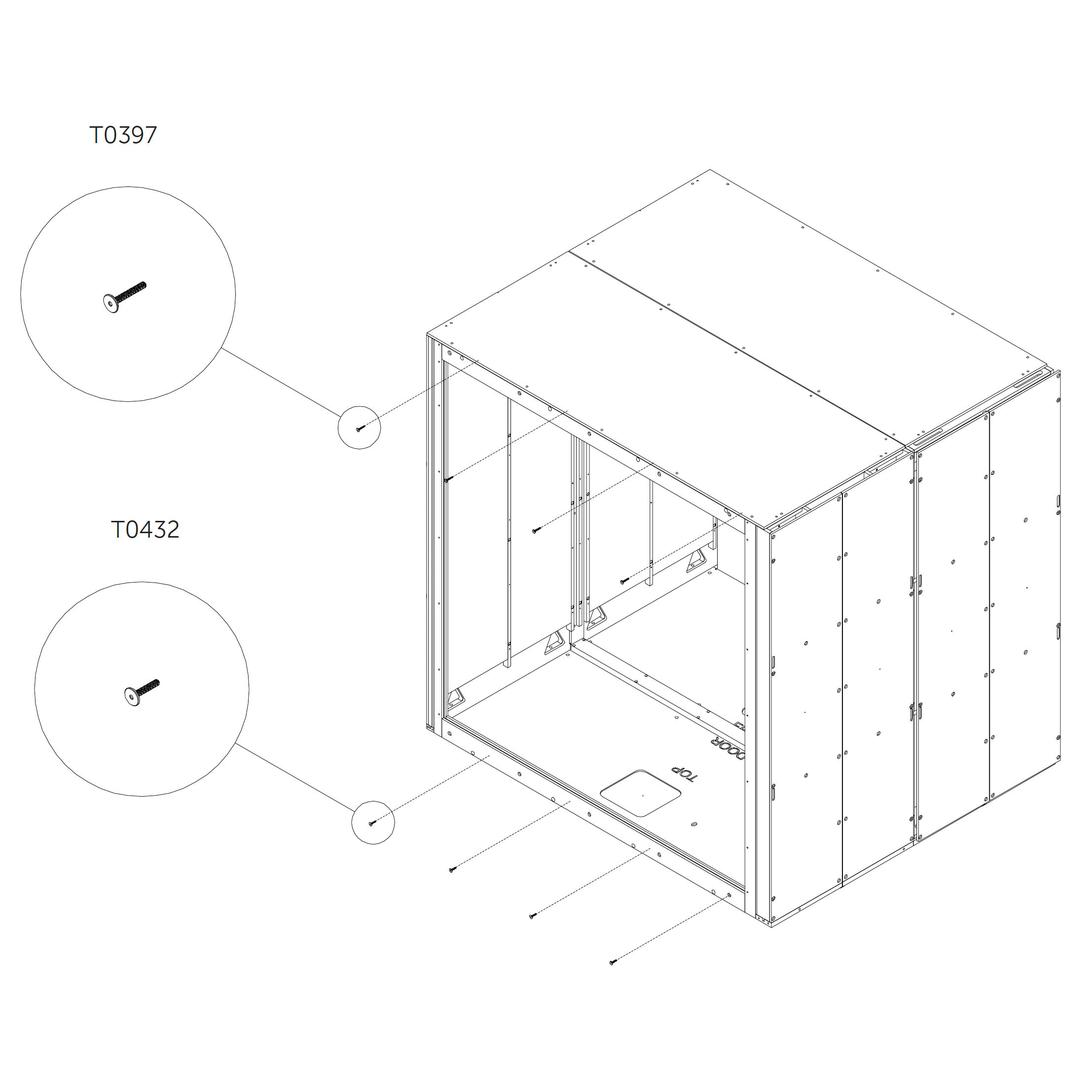
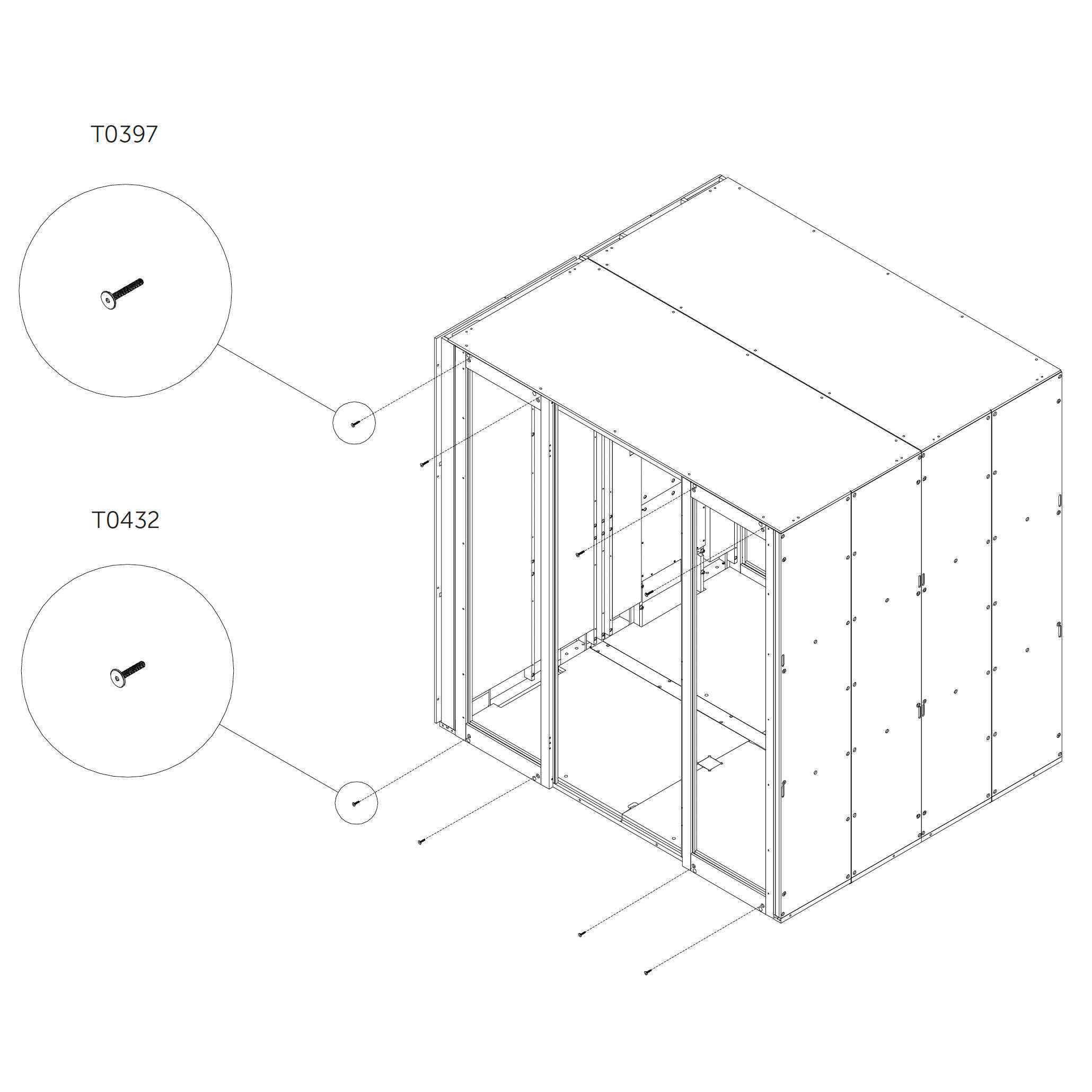
17. Final frame fixation
Secure the bottom and top parts of the frame using additional screws from the inner side as shown.
Parts used:
M6×40 mm hex head metric screw | T0397 | 2×
M6×30 mm hex head metric screw | T0432 | 2×
Cord connection
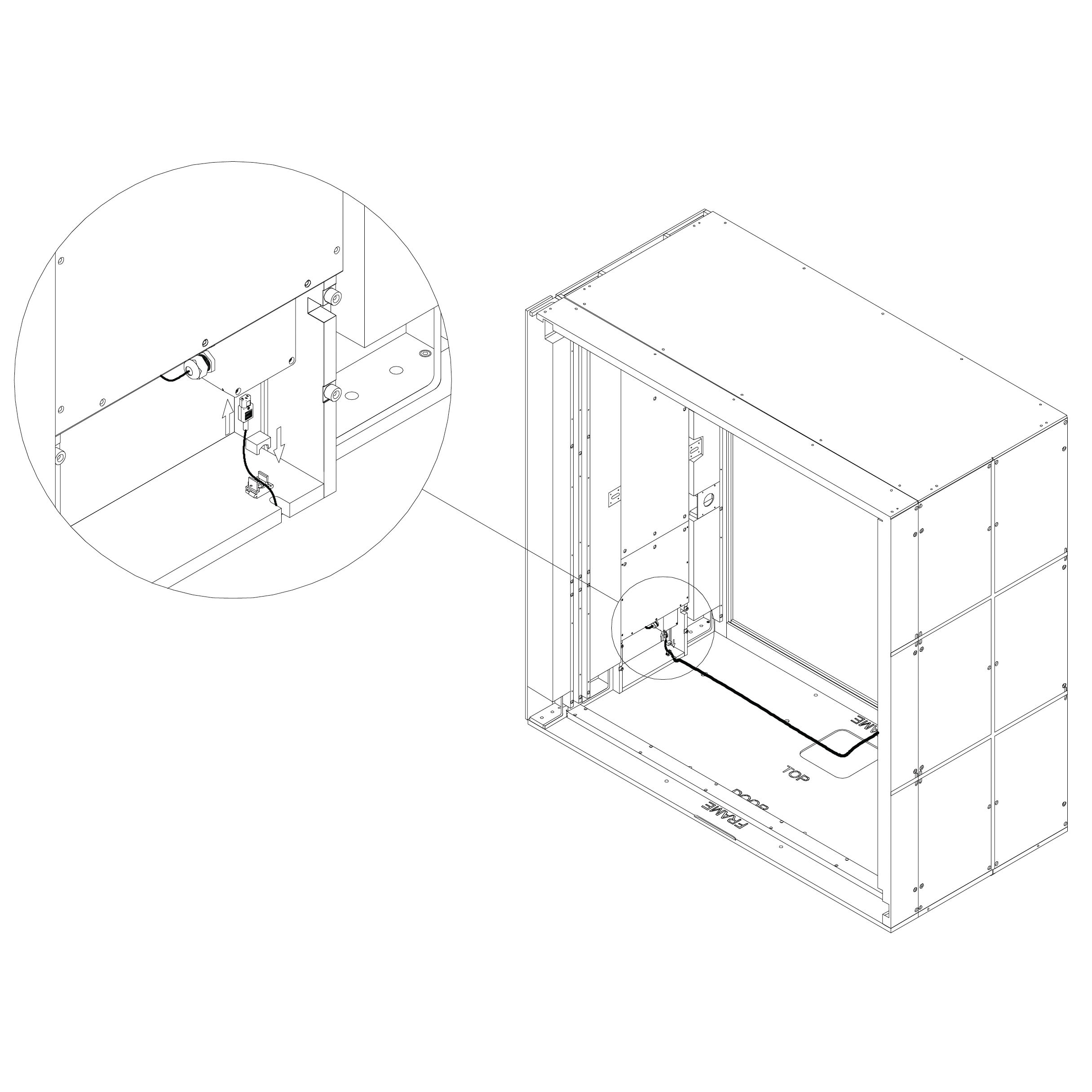
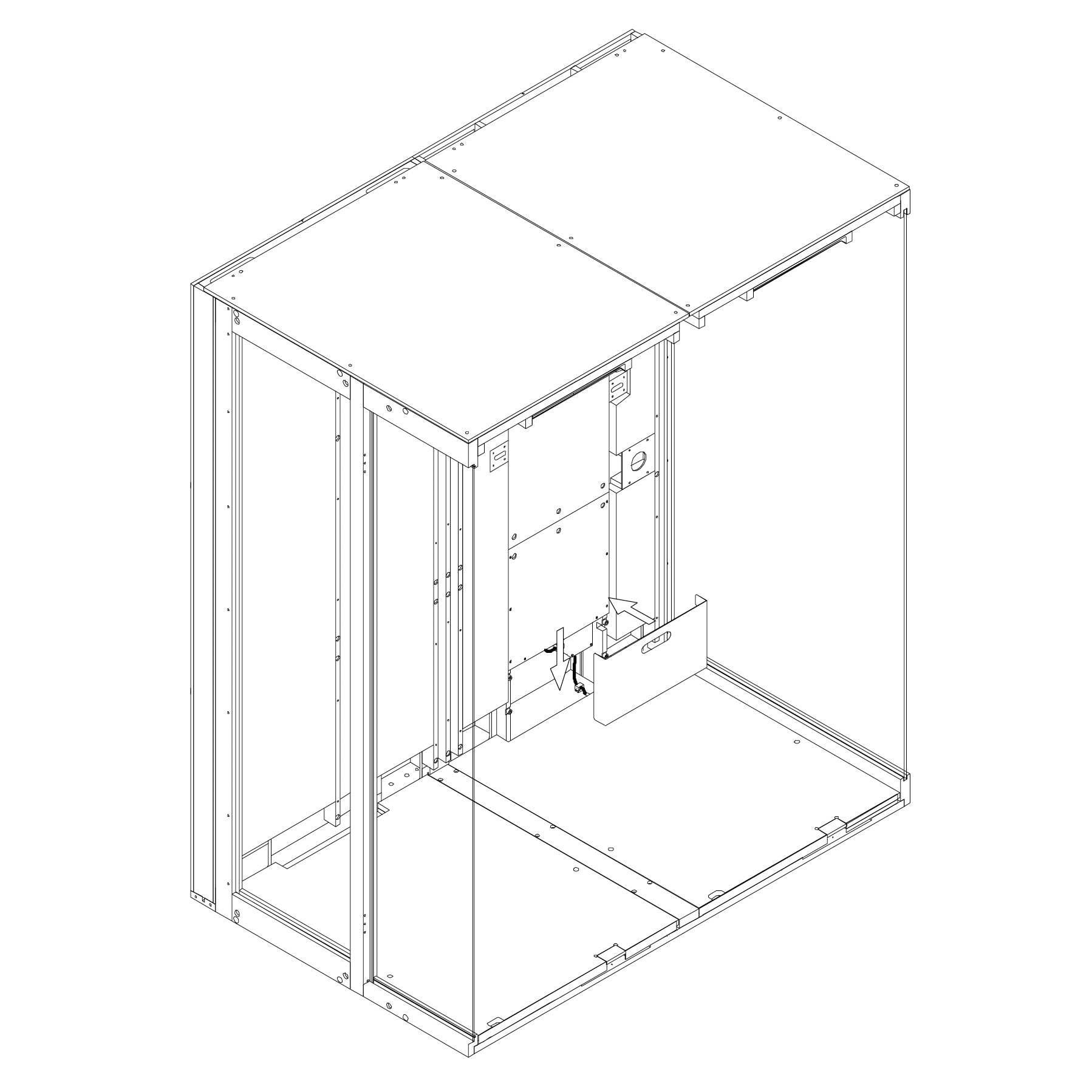
18. Connect the Power Supply Cord
Connect the power cord to the connector at the bottom of the powerbox.
Secure the cord using the strain relief to prevent accidental unplugging.
Finally, attach the revision door using magnets.
⚠️ Warning:
Parts used:
strain relief | E0508 | 1×
Table
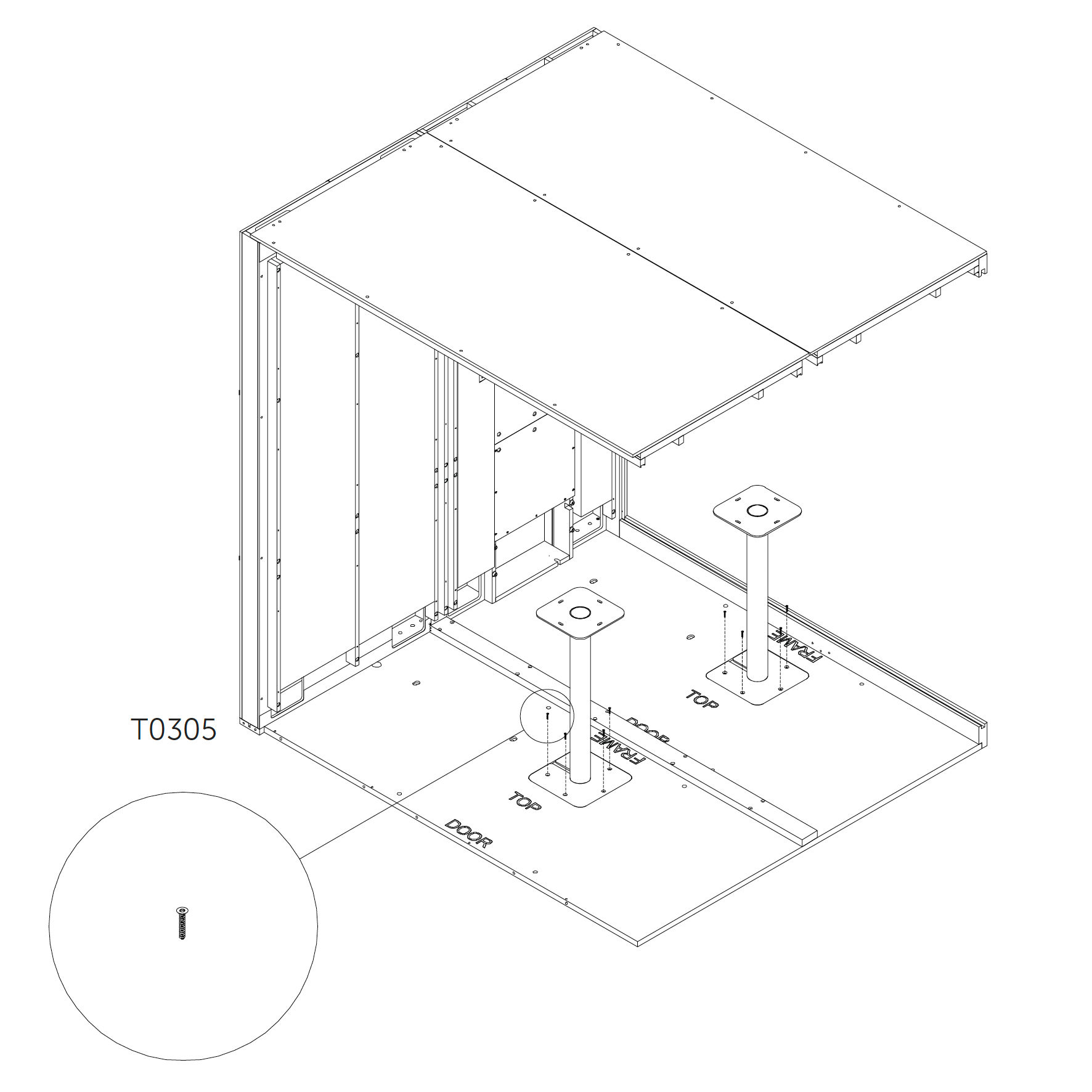
19. Table installation (optional)
Insert the table base into the cutout on the floor and fasten it using metric screws.
Place the tabletop on the base and secure it using wood screws.
Parts used:
M4×10 mm metric screw | T0423 | 8×
wood screw 6×25 mm | T0305 | 8×
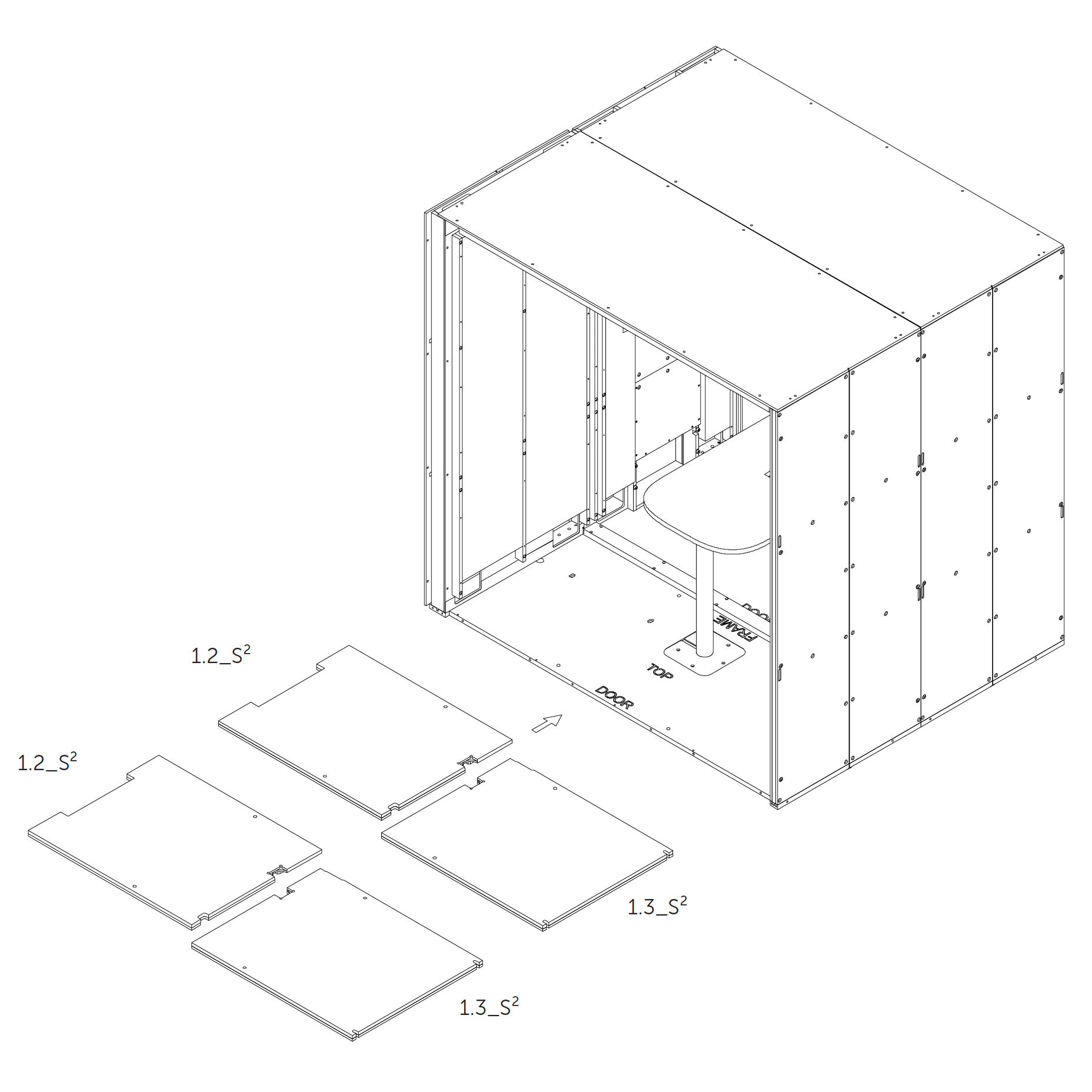
20. Add Floor Insulation 1.2_S², 1.3_S²
Place the floor insulation panels 1.2_S² and 1.3_S² into the corresponding sections on the floor.
21. Cover Floor Cutouts (if no table is installed) If the Microoffice is assembled without a table, insert the wooden plugs into the cutouts in the floor.
Door frame
22. Install the Door Frame 5.1.4_S², 5.1.10_S², 5.1.6_S², 5.1.2_S², 5.1.5_S², 5.1.9_S², 5.1.3_S², 5.1.1_S², 5.1.7_S², 5.1.8_S²
Place the door frame in position by inserting the bottom section first.
Parts used:
M6×120 mm hex head metric screw | T0430 | 4×
M6×65 mm hex head metric screw | T0431 | 4×
M6×30 mm hex head metric screw | T0432 | 6×
M6×120 mm hex head metric screw | T0397 | 6×
washer | T0438 | 8×
23. Anchor Door Frame
Anchor the door frame to the structure using screws as shown; do not tighten fully.
Repeat on both sides of the frame to secure evenly.
Parts used:
M6×120 mm hex head | T0430 | 2×
washer | T0438 | 2×
M6×65 mm hex head | T0431 | 2×
washer | T0438 | 2×
M6×120 mm hex head | T0397 | 2×
M6×30 mm hex head | T0432 | 2×
24. Place and Anchor Door Frame
Position the top frame piece over the door opening.
Secure the frame using screws as shown; do not overtighten.
Parts used:
M6×120 mm hex head | T0397 | 2×
M6×30 mm hex head | T0432 | 2×
Tighten All Screws
25. Tighten All Screws
Fully tighten all screws installed in the previous steps.
Ensure that all joints are secure and panels are properly aligned.
Rear Glazing
26. Install Rear Glass Panels 5.2_S² (Rear glazing)
Clean the edges of each glass panel using the glass cleaner.
Apply the sealing profile along the edges as shown.
Insert the first two glass panels into the groove, starting from the top edge and moving to the bottom.
Shift each panel sideways to lock into position.
27. Install Rear Glass Panel
Clean the edge of the glass with the glass cleaner.
Apply sealing profile to the edge of the glass as shown.
Insert the glass into the groove and shift into position (top edge first, then bottom).
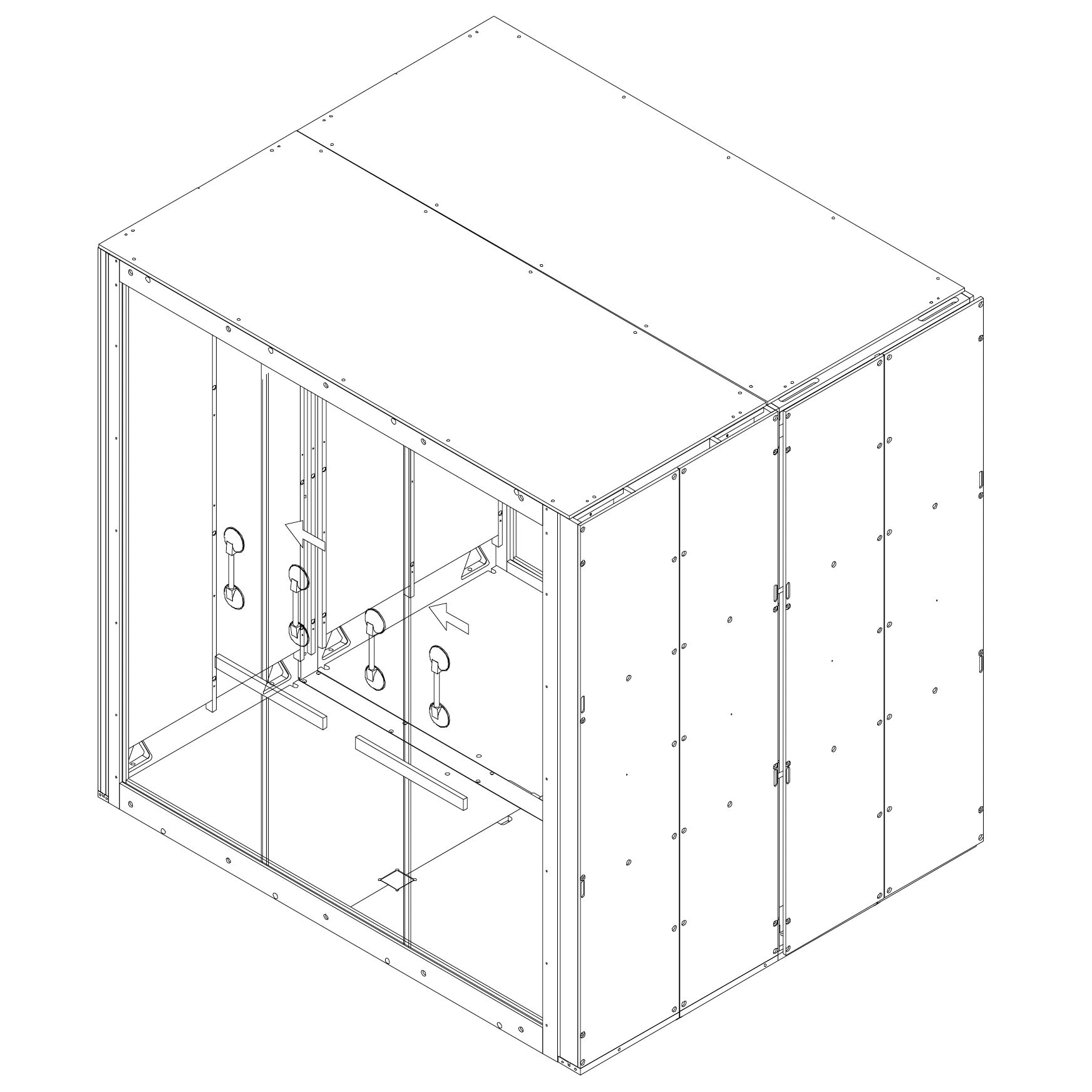
28. Align and Press Rear Glass
Attach suction cups to the glass and press the spirit level against the surface to align it.
Press the glass panels together tightly.
Move suction cups to the top part of the glass and press again.
Repeat the press at the bottom of the glass for final alignment.
Shift all glass panels to the left (from outside view).
Door Installation
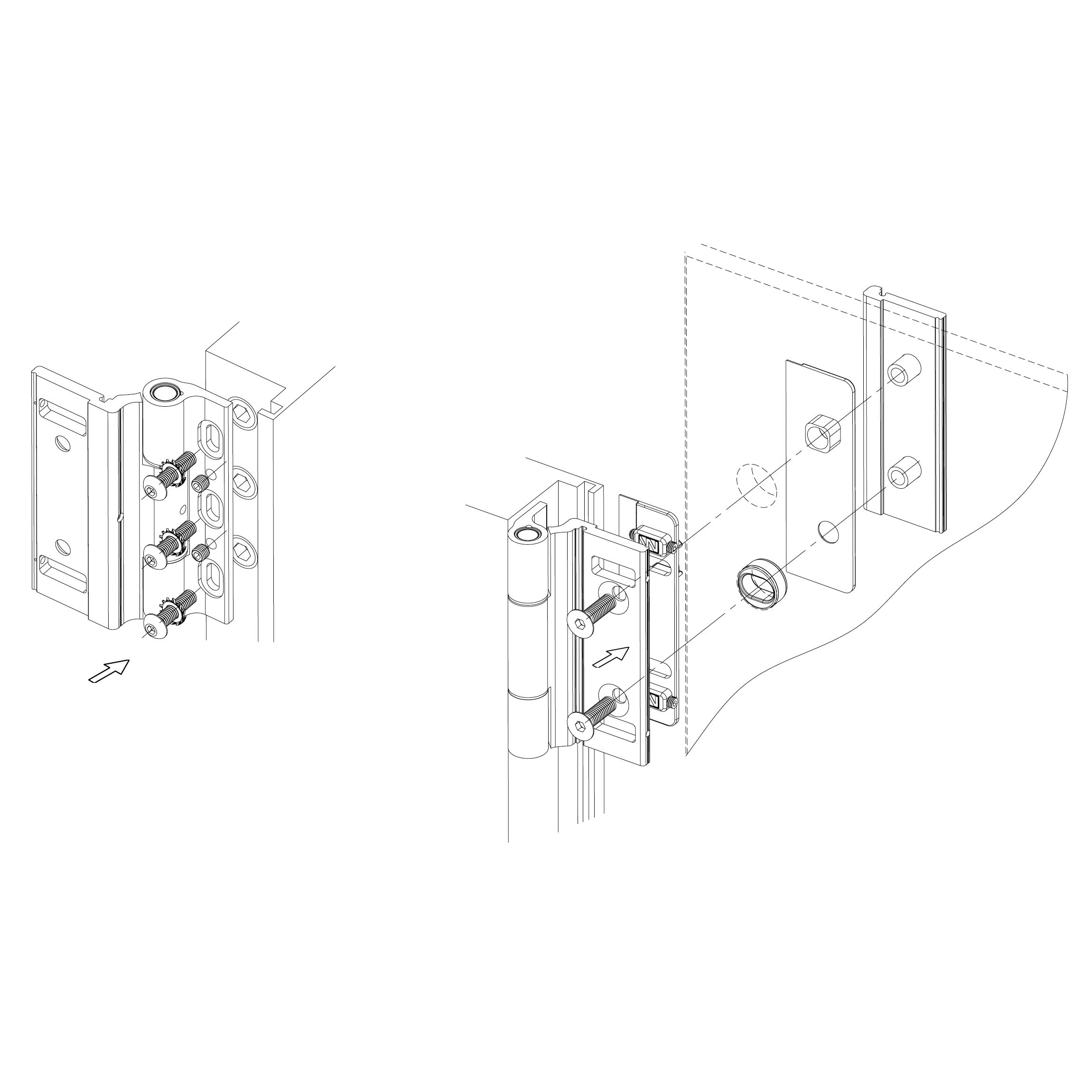
29. Install Hinges
Mount the hinges to the frame using metric screws and predrilled holes as shown.
Position the door leaf and align it with the hinge plates.
Insert hinge pins to secure the door.
Parts used:
30. Position Door Glass
Place two 6 mm plastic spacers on the bottom of the door frame.
Rest the bottom edge of the door glass on the spacers.
Raise the glass into a vertical position and insert the hinges into the predrilled holes.
Insert at least two 4 mm plastic spacers on each side to center the door.
Tighten the hinge screws using hex key no. 4 with a torque wrench set to 15 N·m.
Remove all spacers.
Attach hinge covers to the hinges (recommended: remove only half the tape liner on the double-sided adhesive).
31. Install Handle
Insert the two parts of the handle through the hole in the glass.
Use the enclosed M6 screw with hex socket bottom head.
Use hex key no. 4 to tighten.
Place a plastic spacer between the screw and glass to prevent contact.
Tighten securely.
Parts used:
32. Revision Door Installation Place the revision door (2.12_S⁴) using magnets as shown.
Carpet
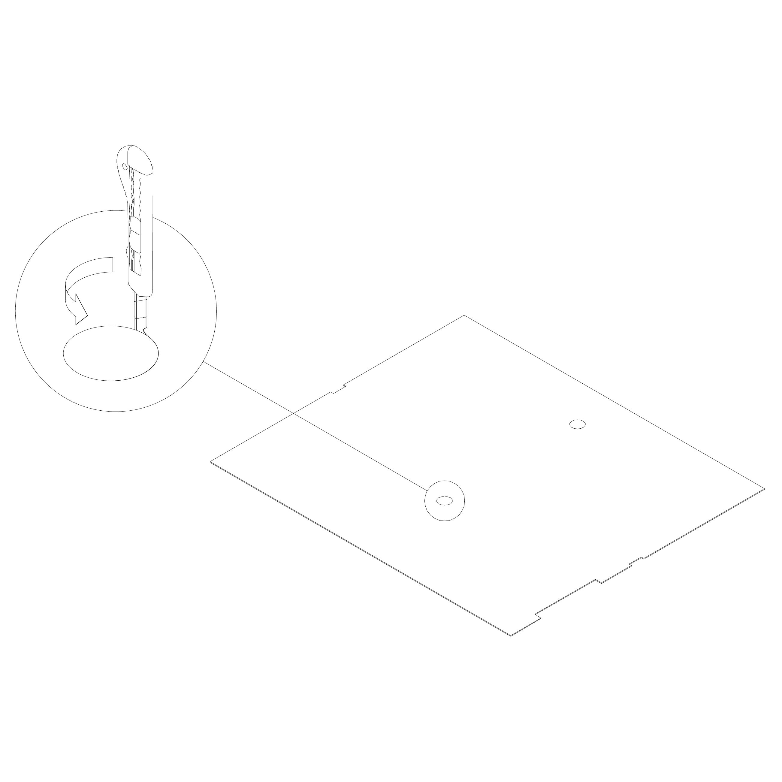
33. Install Carpet 1.2.3_S² (carpet)
If your version of the Microoffice includes a table, use a knife to cut out the hole along the perforated marks on the carpet.
Lay the carpet onto the rubber bands in the pod.
Ceiling light panel
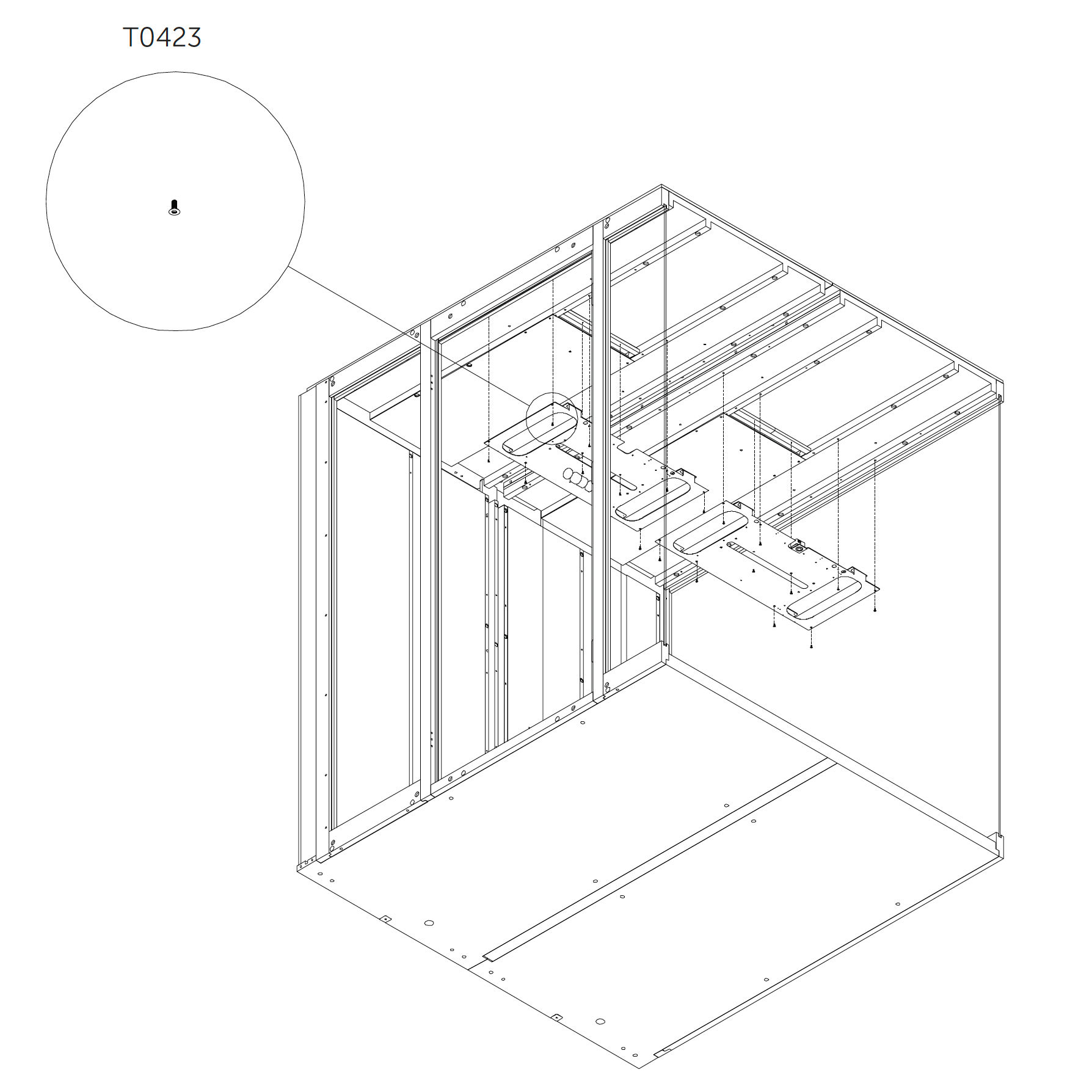
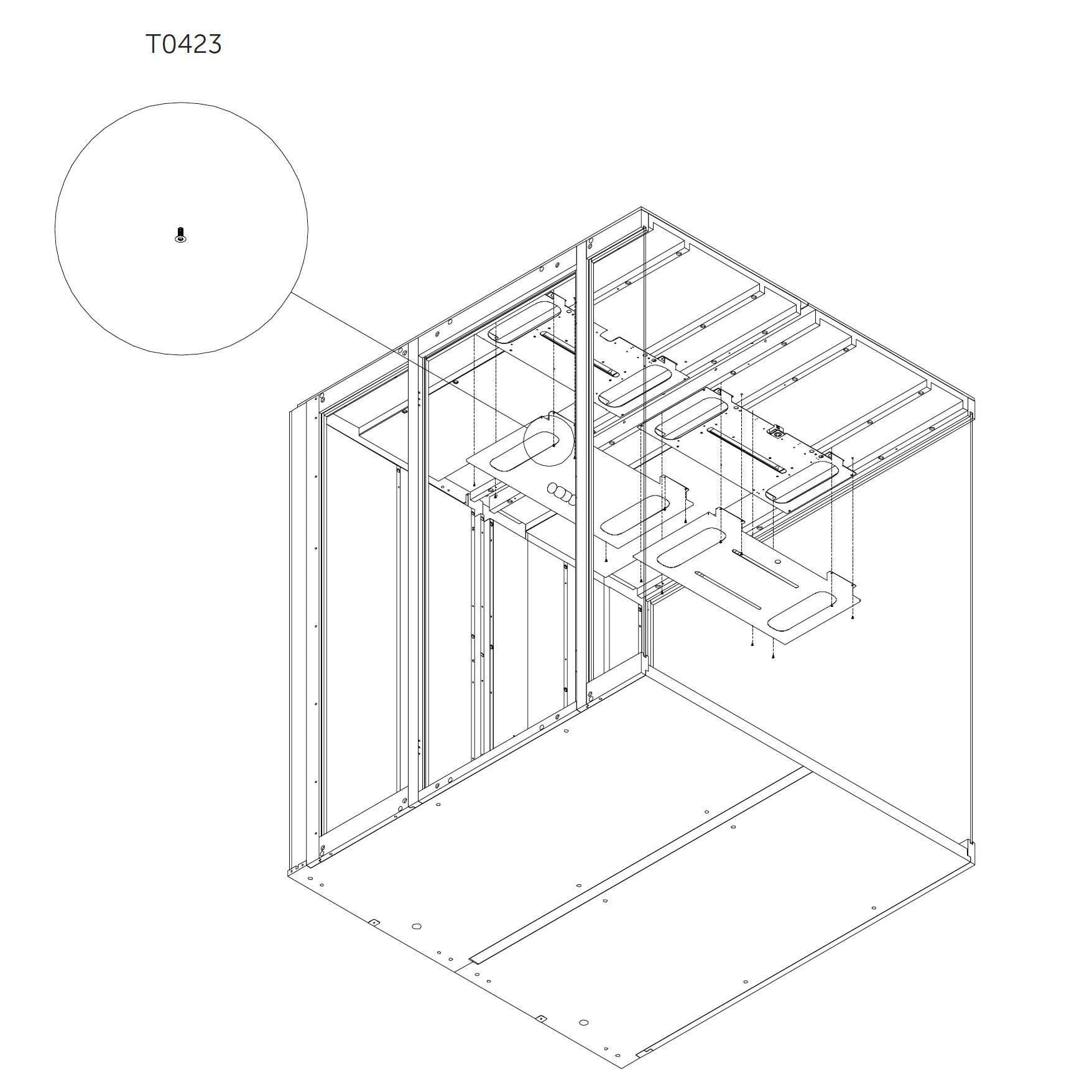
34. Ceiling Light Panel – Part 1 9.2_S (ceiling light panel)
Attach component K0353 to the roof panel using screws.
Parts used:
M4×10 mm screw | T0423 | 18×
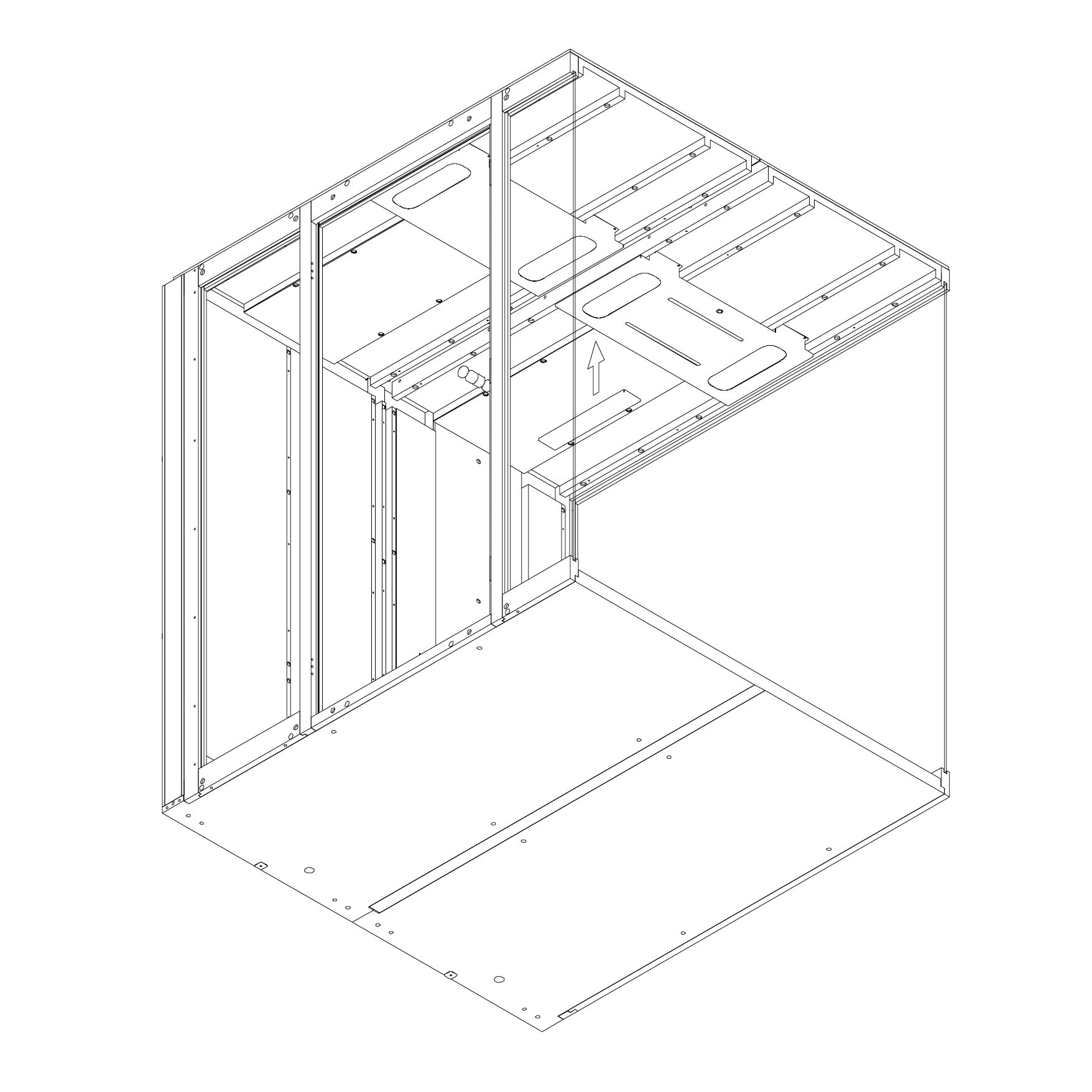
35. Ceiling Light Panel – Part 2
Attach components K0351 and K0390 to the roof panel using screws.
Parts used:
M4×10 mm screw | T0423 | 6×
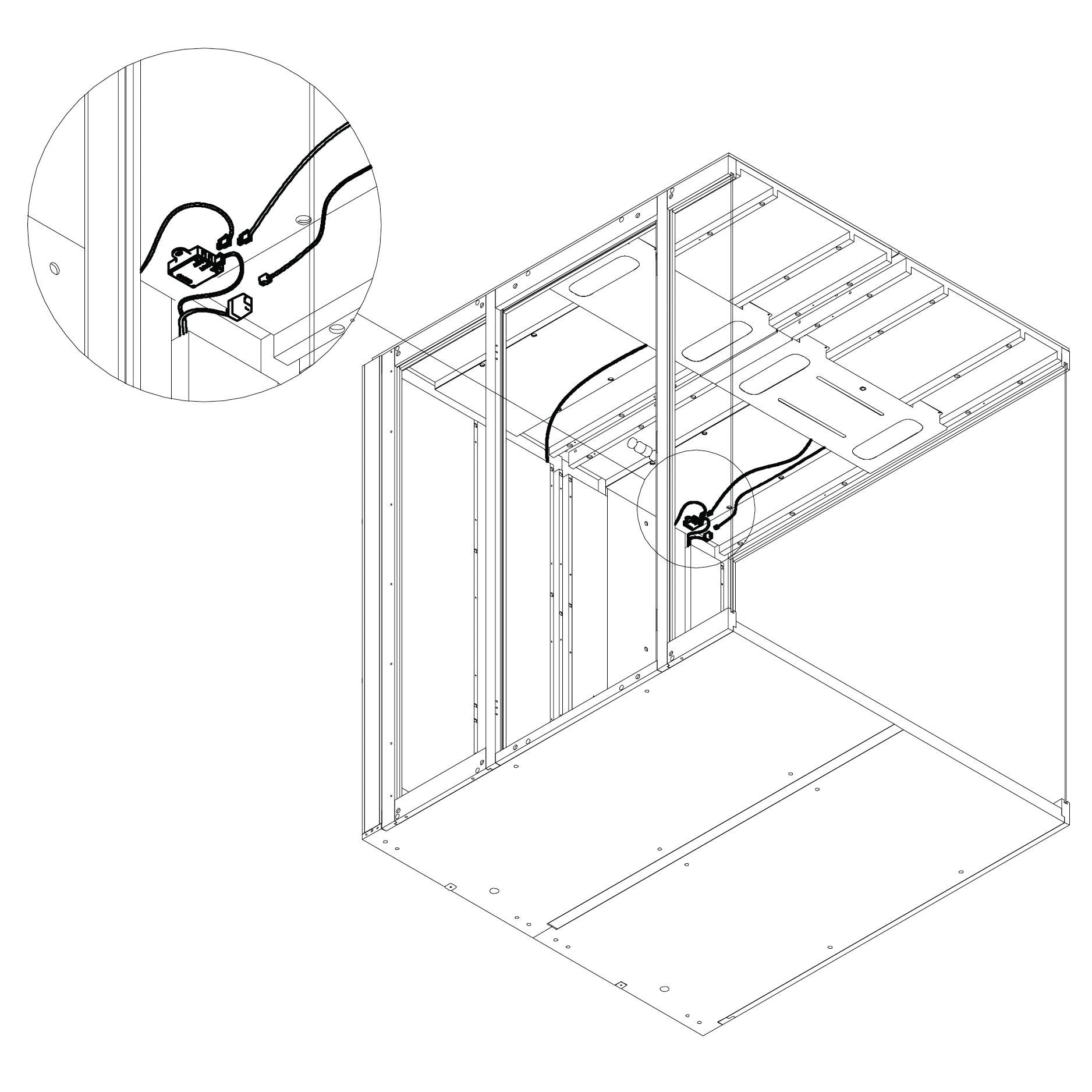
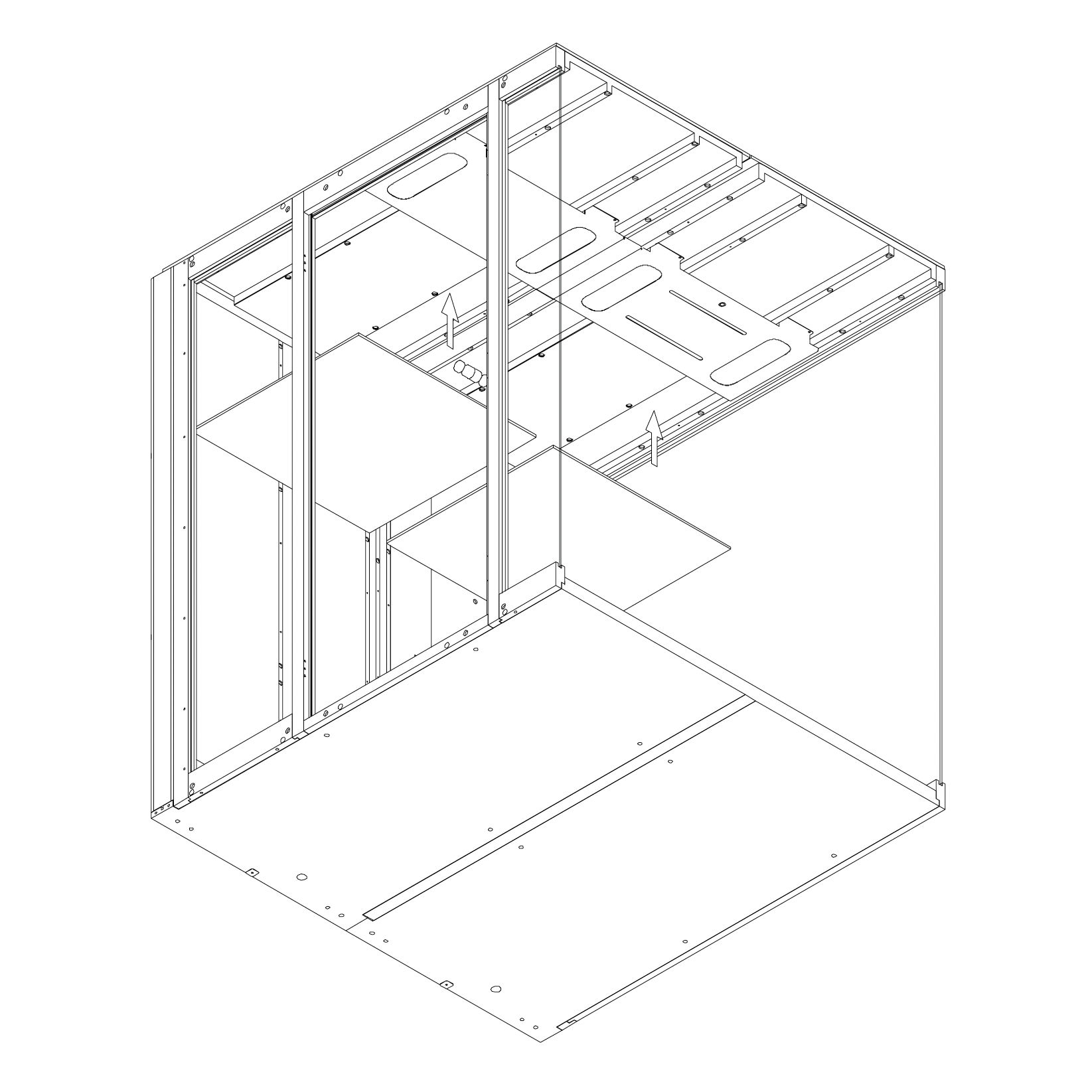
36. Install Magnetic Panel Place part K0389 using magnets as shown.
37. Connect Light Cables Connect the light power cable and the presence detector cable to their connector located in Dock 2.0_S².
Internal panels
38. Attach Inner Panel 6.3.2_S² Attach the inner panels 6.3.2_S² using magnets as shown.
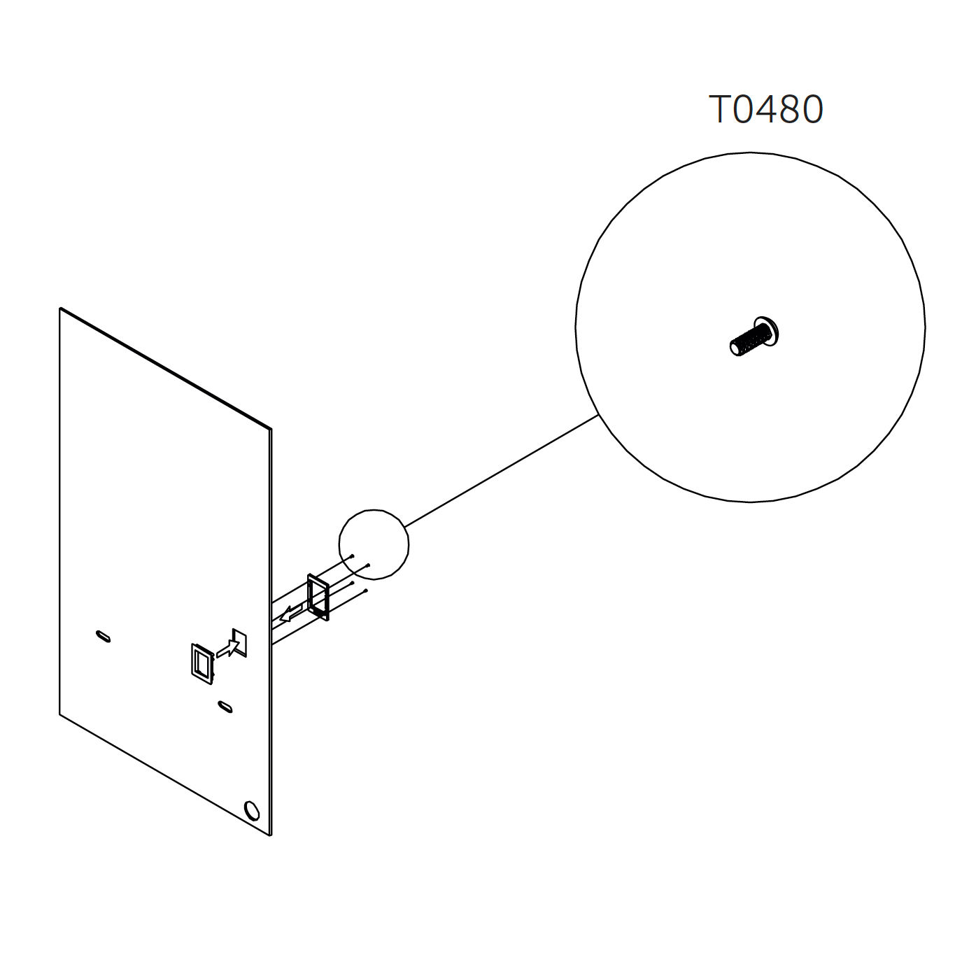
39. Display Installation
Attach the display to interior panel 6.4_S using screws as shown.
Parts used:
M3×8 mm button head | T0480 | 8×
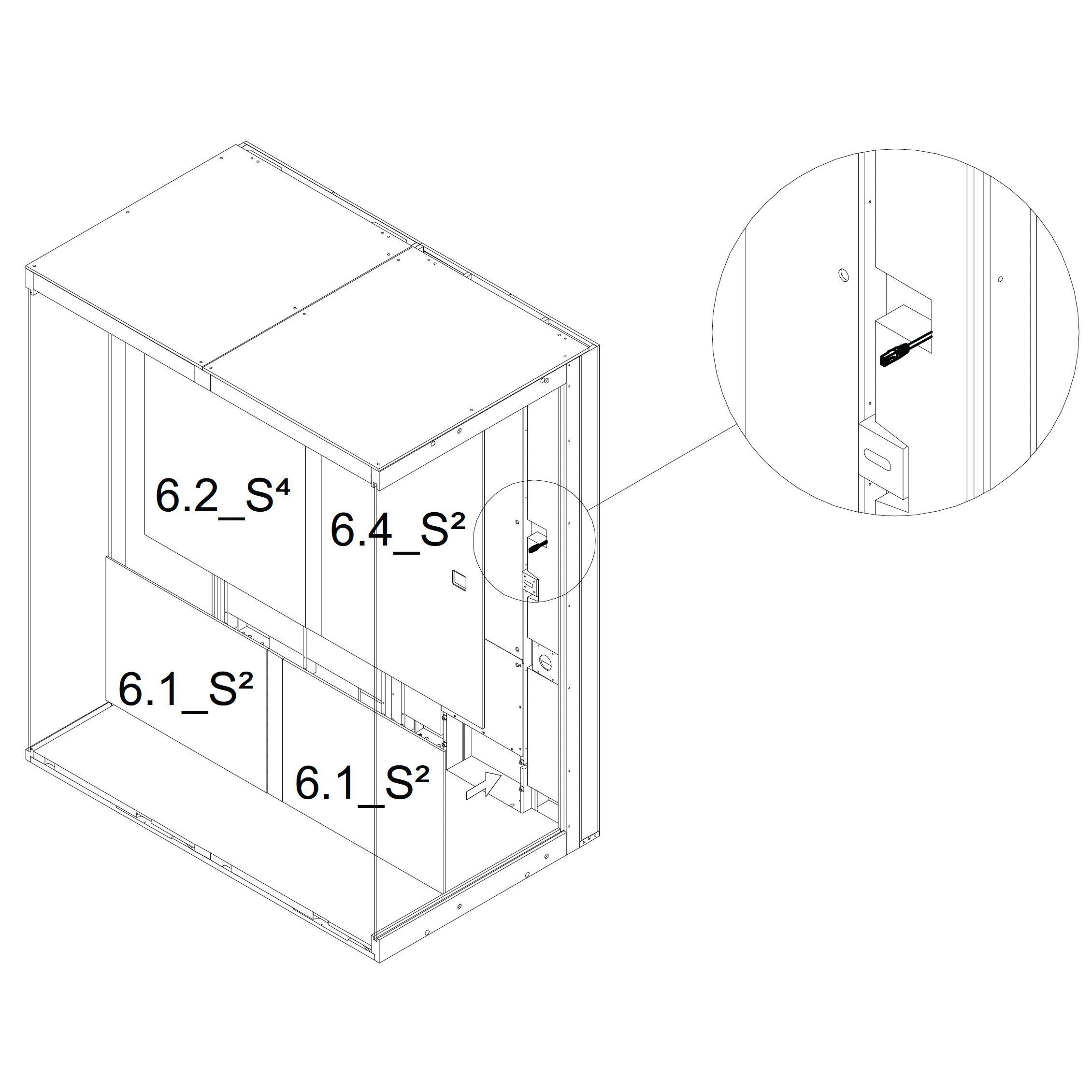
40. Connect LAN Cable Before placing panels 6.2_S², 6.4_S², and 6.2_S⁴, plug the LAN cable into the control display.
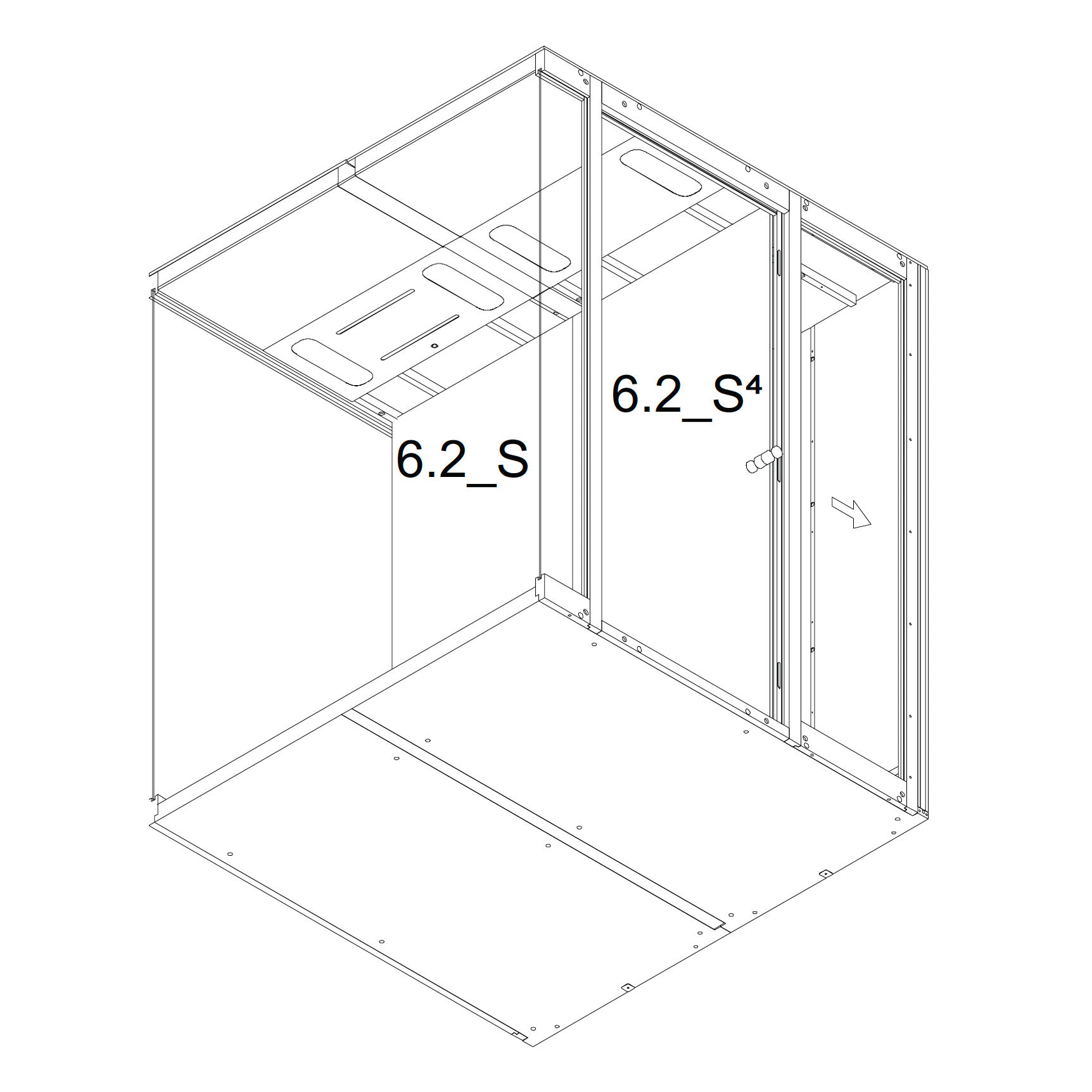
41. Attach Remaining Inner Panels Continue attaching the inner panels using magnets as shown:
6.2_S
6.2_S⁴
6.4_S⁴
6.3.2_S²
Magnets
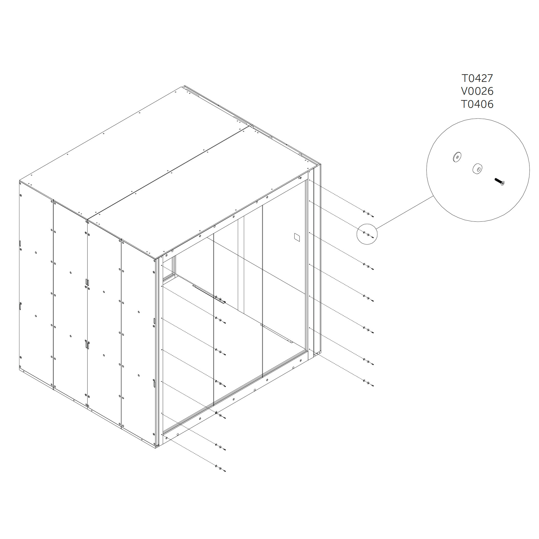
42. Install Magnets
Attach the magnets to the rear and door frame using screws and washers as shown.
Parts used:
M4×20 mm screw | T0427 | 28×
Magnet | V0438 | 28×
Washer | T0046 | 28×
External panels
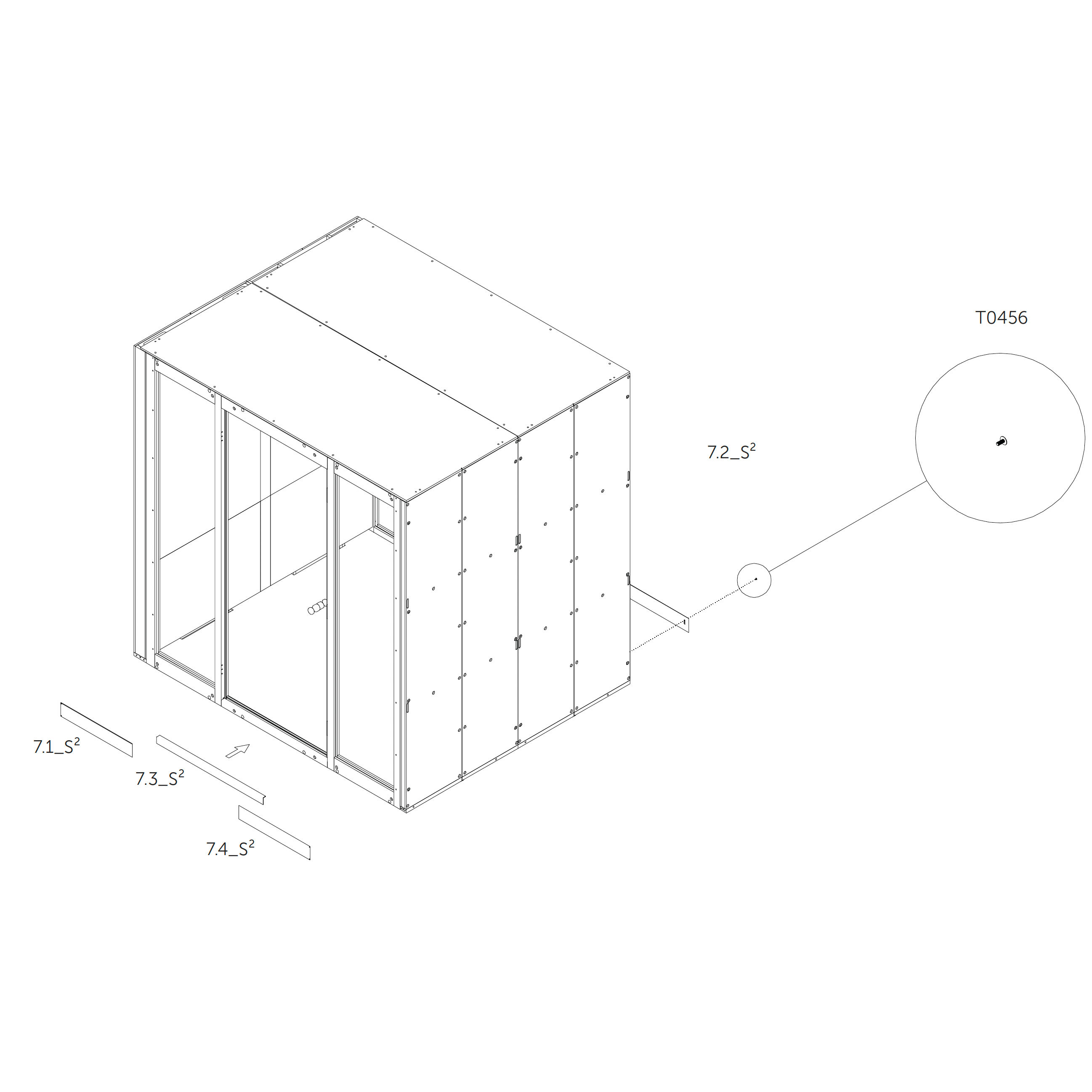
43. Attach External Panels (Front Side)
Attach the external panels 71.1_S² and 73.5_S² using magnets.
Attach the external panel 72.2_S² using metric screws.
Parts used:
M4×16 mm screw | T0456 | × (quantity not specified — confirm based on screw count in images)
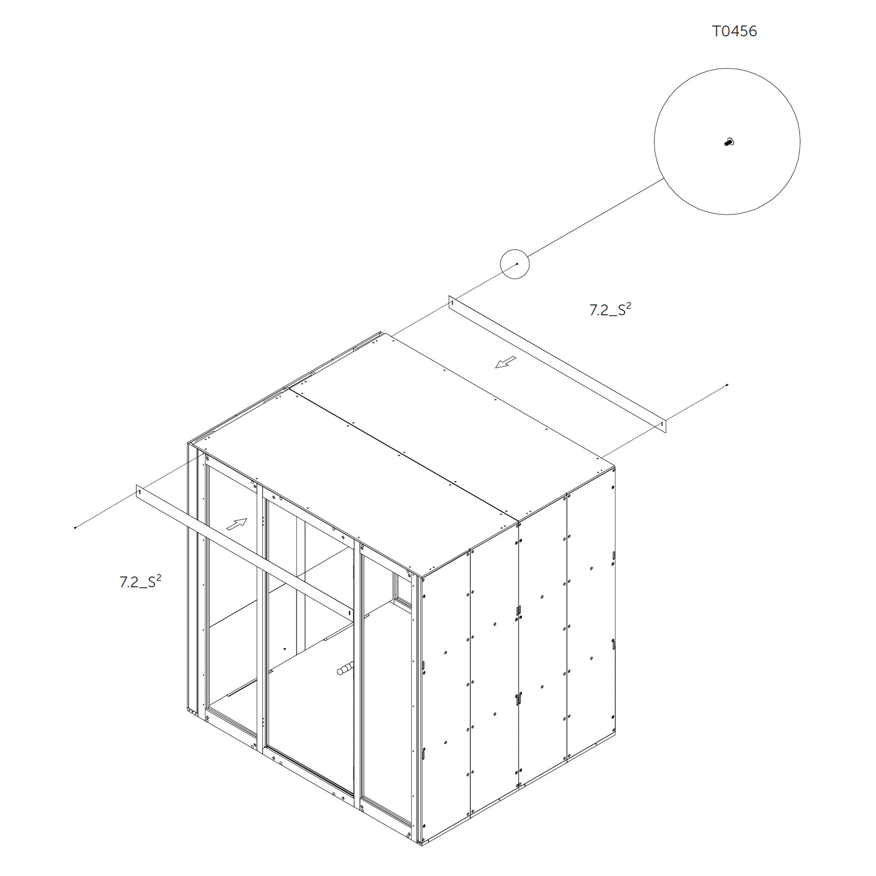
44. Attach External Panels (Top Side)
Attach the external panels 72.5_S² using metric screws.
Parts used:
M4×16 mm screw | T0456 | × (quantity not specified — confirm based on screw count in images)
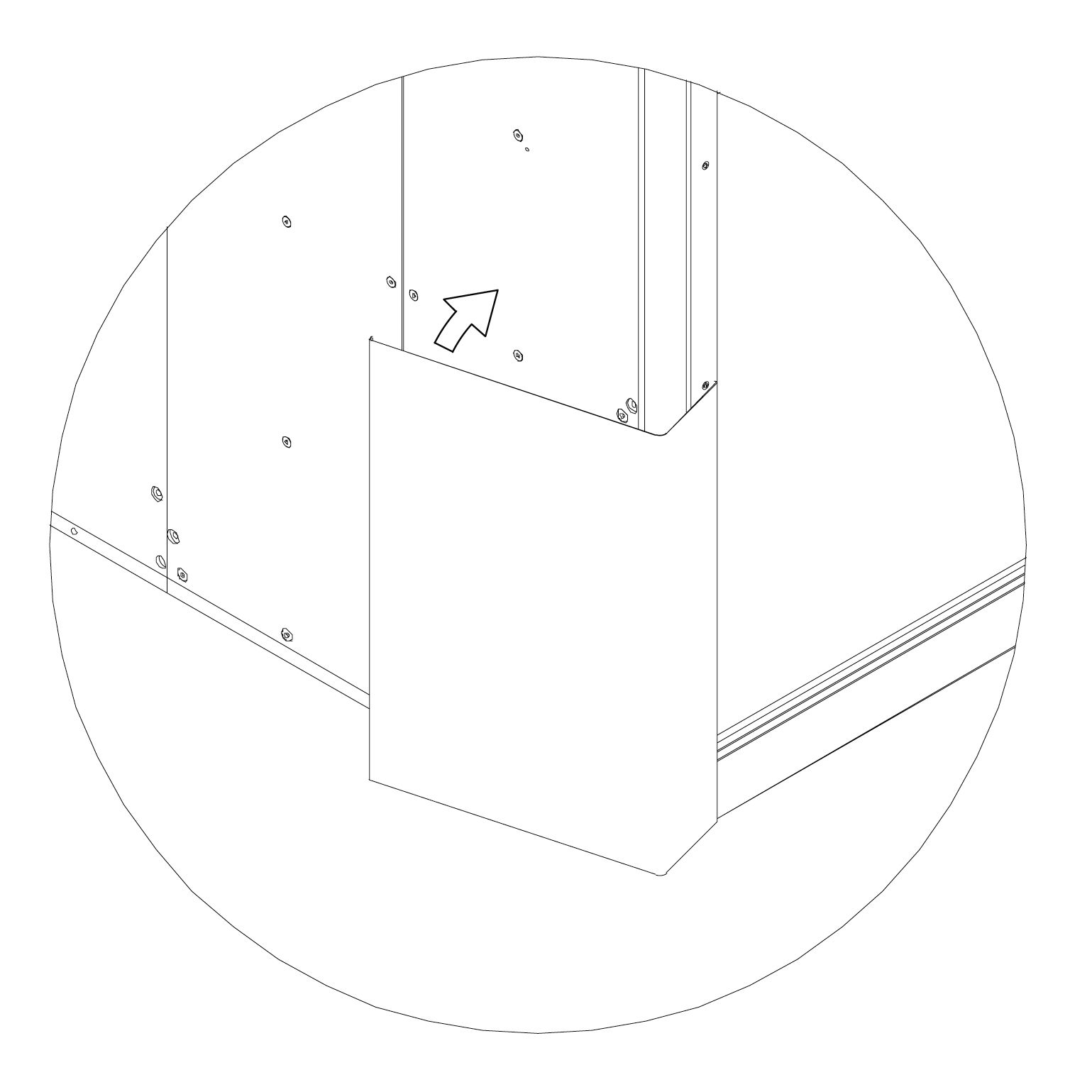
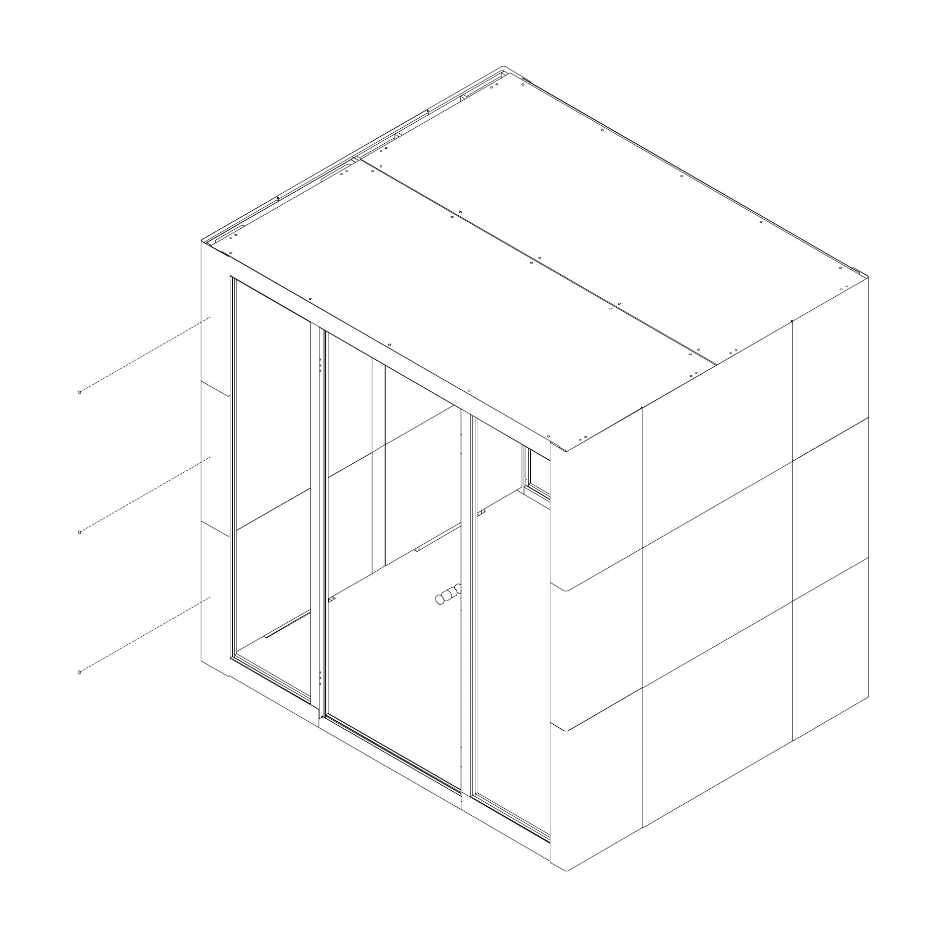
45. Attach External Panels (Side Wall) Attach the external panels using magnets as shown; start from the bottom.
Parts used (per side wall, mirrored on both sides):
Panel | 72.5_S | 2×
Panel | 74.5_S | 2×
Panel | 76.5_S | 2×
Panel | 77.5_S | 2×
Panel | 79.5_S | 2×
Panel | 71.5_S | 2×
Panel | 73.5_S | 2×
Door damping
46. Install Door Dampers Attach the self-adhesive door dampers in the middle of the external panel as shown.
Parts used:
Door damping | T0471 | 1×
Roof cover
47. Install Roof Cover Put the roof cover on top of the Microoffice and anchor it using screws.
Parts used:
Roof cover | 9.1_S²/⁴ | 1×
Wood screw | T0491 | 12×
Final Checklist
48. Enjoy the Silence