Step-by-step instructions for assembling the FOCUS acoustic pod by SilentLab.
Product Information
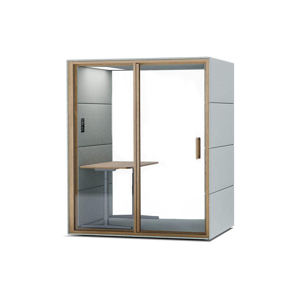
FOCUS
Private soundproof pod for undisturbed work.
1 person
FOCUS is an acoustic pod dedicated for deep concentration and peak performance. Designed to function as a complete workstation, it creates a private, soundproof environment perfect for long-term, uninterrupted focus.
Ergonomic workstation for comfortable productivity
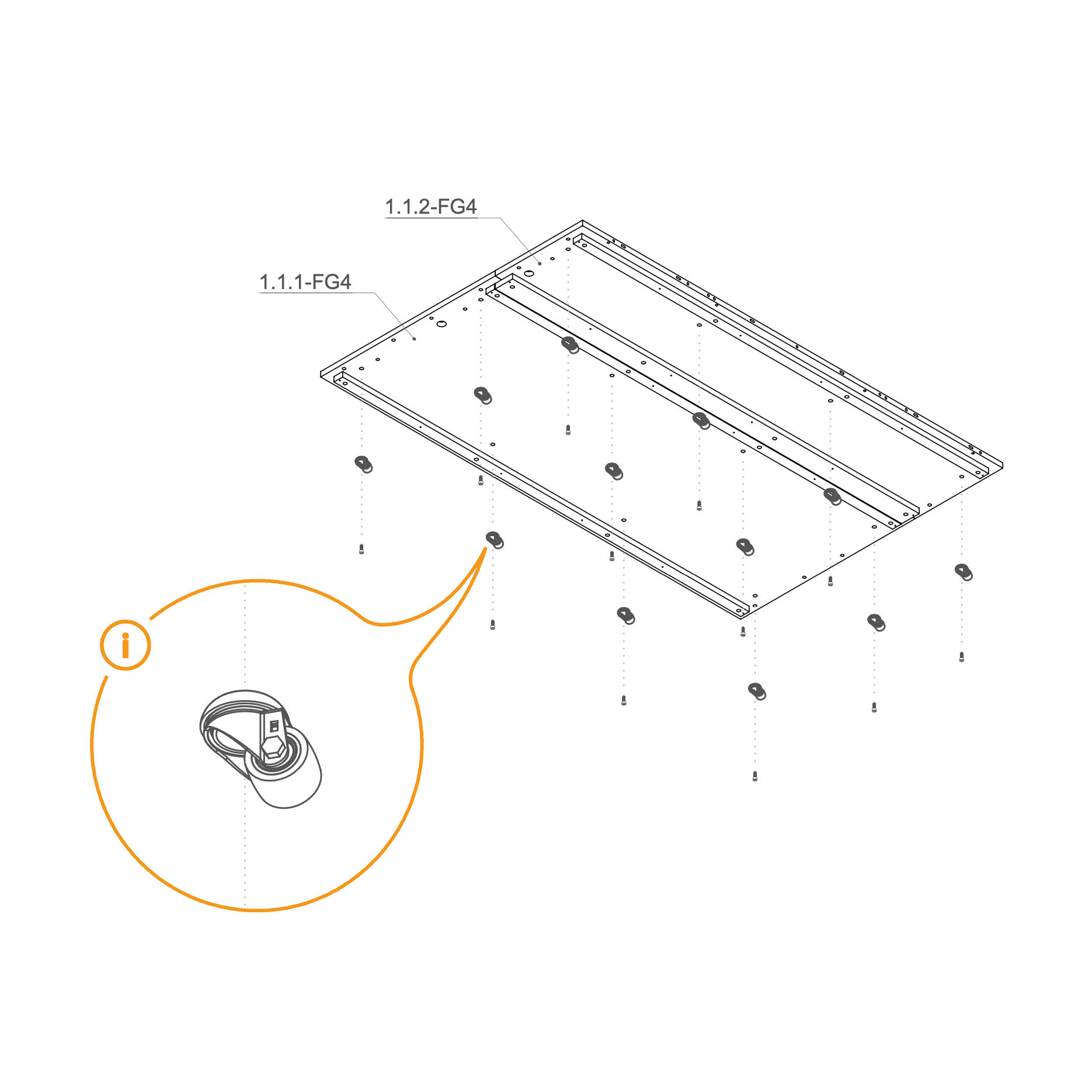
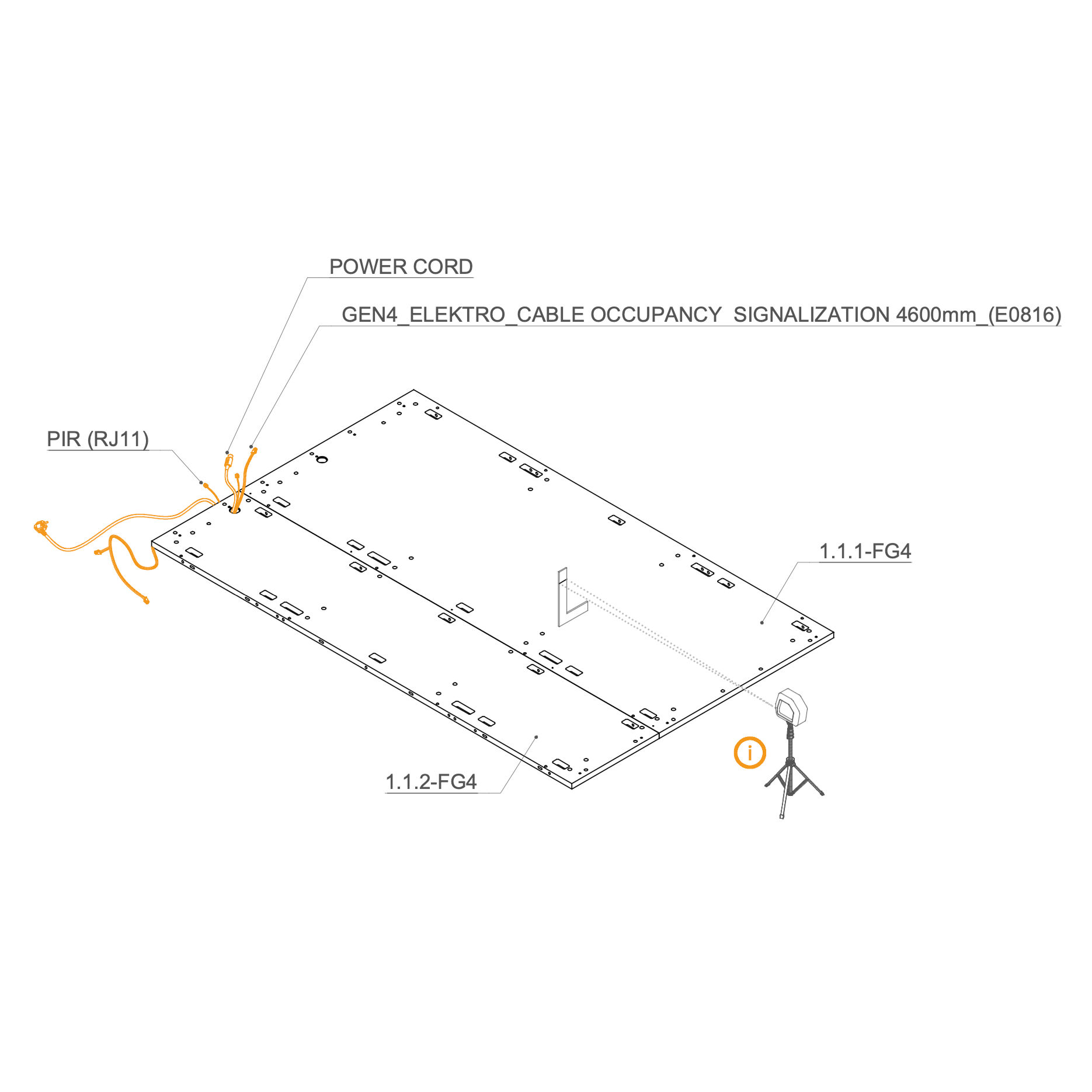
Place floor panel 1.1.1-FG4 and 1.1.2-FG4 on a flat surface.
Use the marked holes in the picture to insert the screws (T0509). If your order includes wheels (V0181), attach them to the same holes using screws M10×25 mm (T0509).
Parts used:
floor panel | 1.1.1-FG4 | 1×
floor panel | 1.1.2-FG4 | 1×
wheel | V0181 | 12×
M10×25 mm bolt | T0509 | 12×
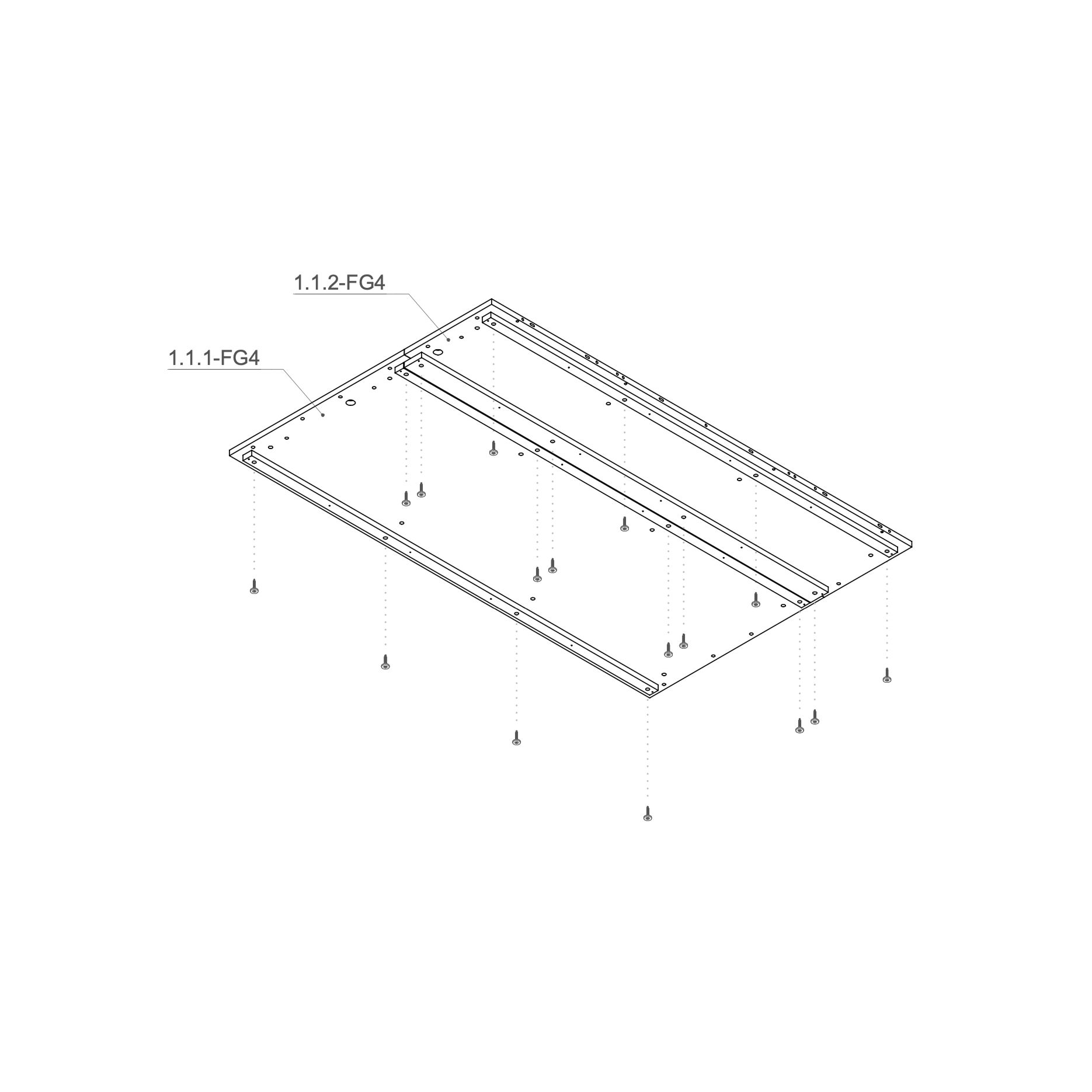
2. Install Leveling Feet
Keep the 1.1.1-FG4 and 1.1.2-FG4 floor panel flipped upside down (bottom side up).
Insert one levelling foot (V0050) into each of the 8 marked holes on the underside of the floor panels.
Using a Phillips head screwdriver, partially screw in the standing feet. Leave approximately 20 mm of clearance to allow for future adjustments—do not fully tighten them at this stage.
Parts used:
floor panel | 1.1.1-FG4 | 1×
floor panel | 1.1.2-FG4 | 1×
leveling foot M10×55 mm | V0050 | 16×
3. Route Cables Through the Hole
Lay the GEN4_ELEKTRO_CABLE OCCUPANCY SIGNALIZATION 4600 mm (E0816), LAN cable (RJ45), and power cord through the hole in the floor panel. Follow the marked path shown in the bottom view, ensuring the cables are not pinched.
Use a laser level and L-angle (or a spirit level) to level the floor. Adjust the height of the standing feet using a Philips head bit.
Parts used:
floor panel | 1.1.1-FG4 | 1×
floor panel | 1.1.2-FG4 | 1×
GEN4_ELEKTRO_CABLE OCCUPANCY SIGNALIZATION 4600 mm | E0816 | 1×
Dock
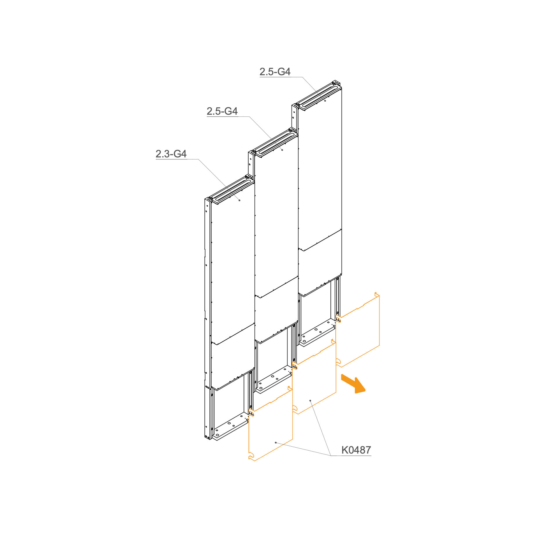
4. Remove Revision Doors
Remove the Revision Doors (K0487) from the docks.
Parts used:
dock panel | 2.3-G4 | 1×
dock panel | 2.5-G4 | 2×
cable cover | K0487 | 3×
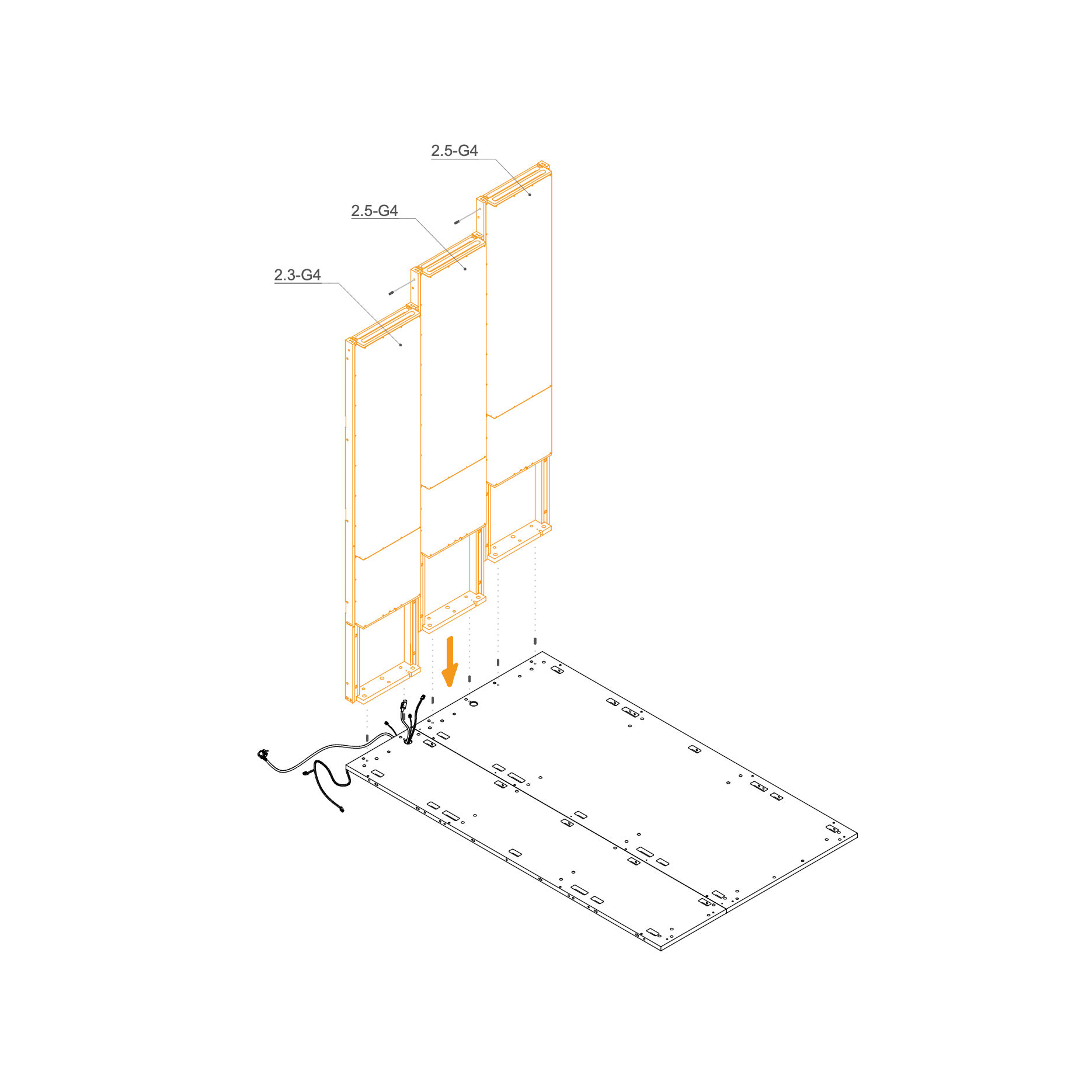
5. Mount Dock on the Floor Panel
Insert 8×30 mm dowel pins (T0122) into the predrilled holes on the floor panel to maintain proper alignment.
Position one dock at a time in place.
Pull the power cord, PIR sensor cable, and signalization cable through the opening in the dock panel for later connection.
Parts used:
dock panel | 2.3-G4 | 1×
dock panel | 2.5-G4 | 2×
dowel pin 8×30 mm | T0122 | 8×
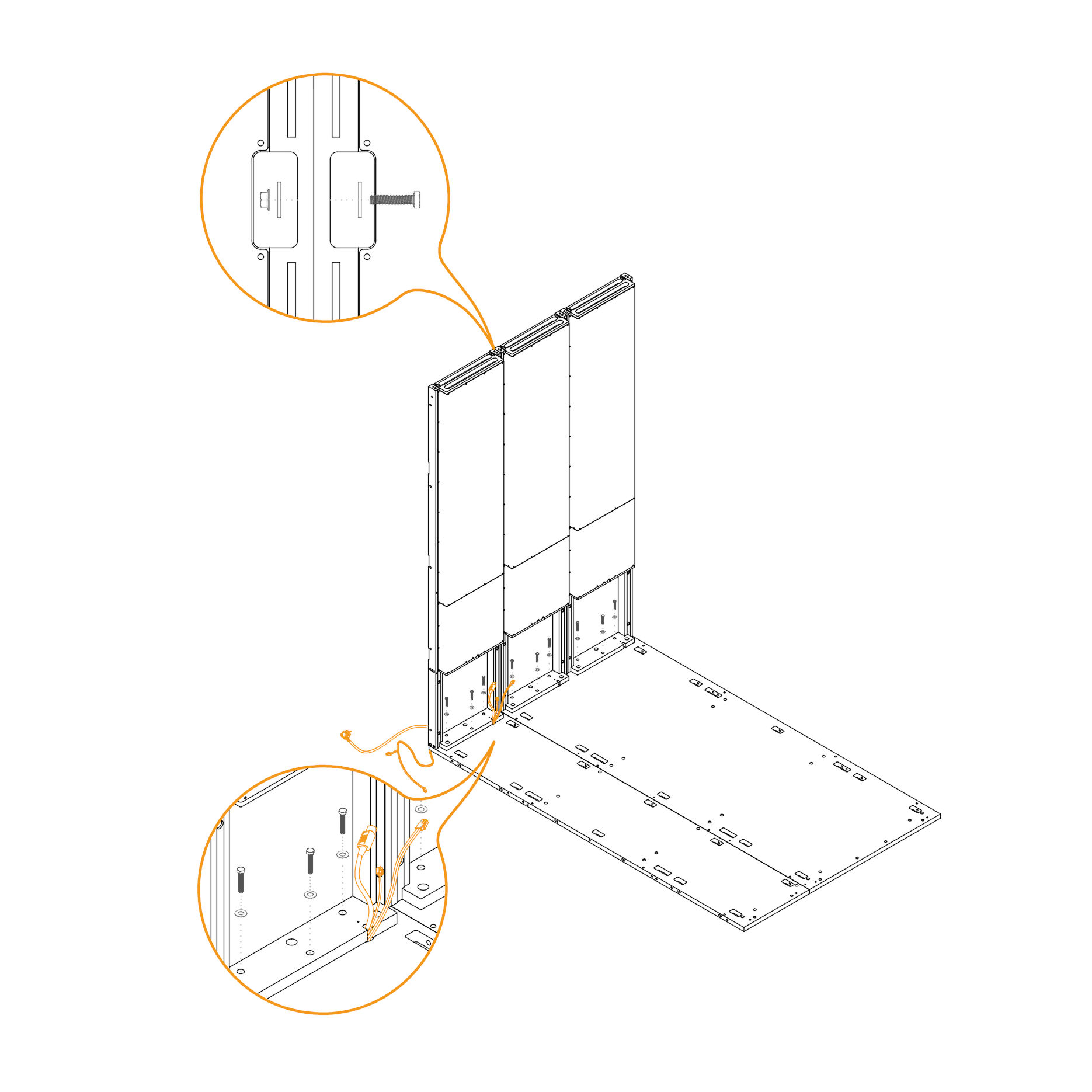
6. Secure the Dock to the Floor Panel
Insert M8×45 mm hex‑head bolts (T0204) through the inner mounting holes.
Place a washer (T0198) underneath each bolt head.
Tighten securely until the bolt and washer are seated flush with the panel surface.
Use the cut-outs on the exterior side of the dock panels to draw them tightly together.
Insert an M6 × 30 mm bolt through the aligned holes. Place a washer under the bolt head and thread an M6 flange nut onto the bolt from the opposite side.
Tighten all bolts firmly to hold the connector in place.
Parts used:
dock panel | 2.3-G4 | 1×
dock panel | 2.5-G4 | 2×
M8×45 mm hex head bolt | T0204 | 9×
washer 8.4×24×2.0 mm | T0198 | 19×
M6×30 mm bolt | T0511 | 10×
flange nut M8 | T0514 | 12×
flange nut M6 | T0514 | 10×
Panel
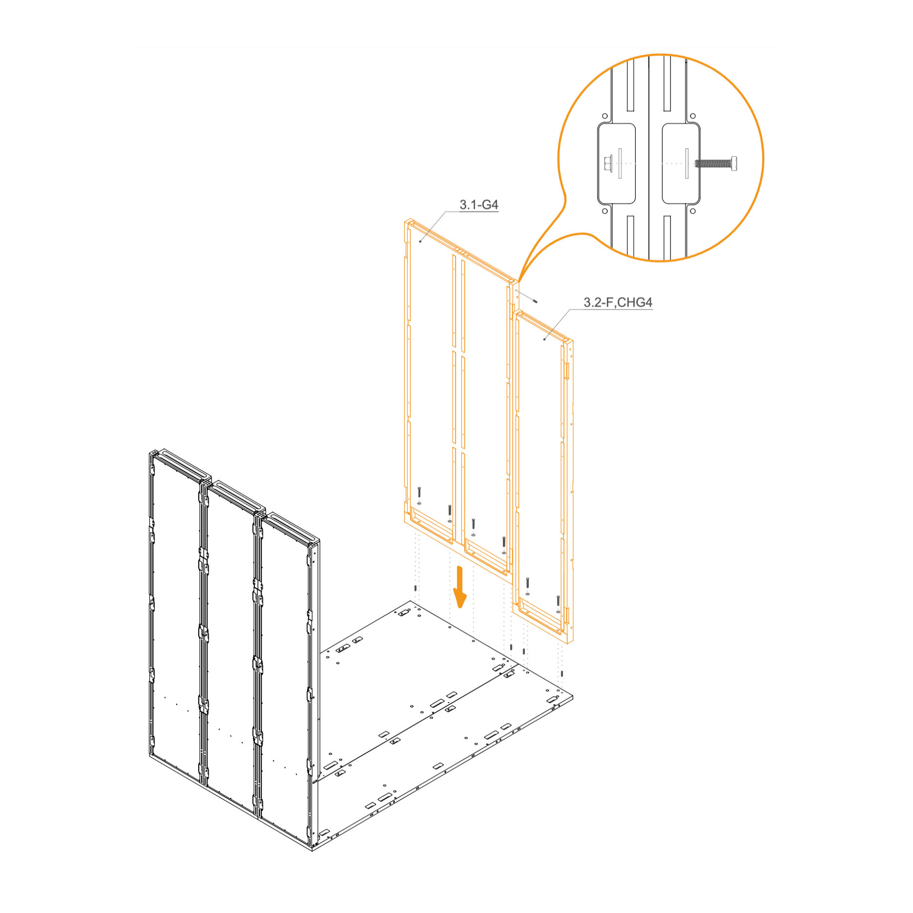
7. Mount Wall Panel to the Floor
Insert dowel pins (T0122) into the predrilled holes in the floor panel.
Align the panel with the pre-drilled holes on the floor panel and the dock frame.
Secure the bottom of the panel using M8×45 mm hex head bolts (T0204) and washers (T0198) through the mounting points.
Parts used:
side panel frame | 3.1-G4 | 1×
side panel | 3.2-F-CHG4 | 1×
M8×45 mm hex head bolt | T0204 | 6×
washer 8.4×24×2.0 mm | T0198 | 6×
dowel pin 8×30 mm | T0122 | 5×
Roof
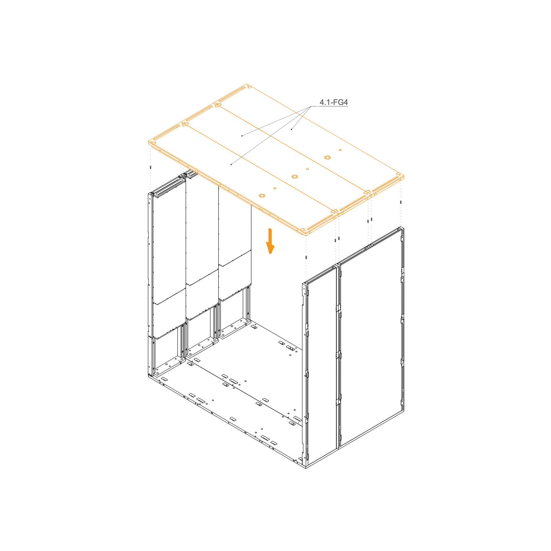
8. Attach Roof
Insert eight dowel pins (T0122) into the designated guide holes along the top edges of the wall panels.
Carefully lower the roof panel onto the structure, aligning the dowel pins with the corresponding holes on the underside of the roof.
Ensure the panel sits flush and is properly seated before proceeding to fasten.
Parts used:
roof panel | 4.1-FG4 | 1×
dowel pin 8×30 mm | T0122 | 12×
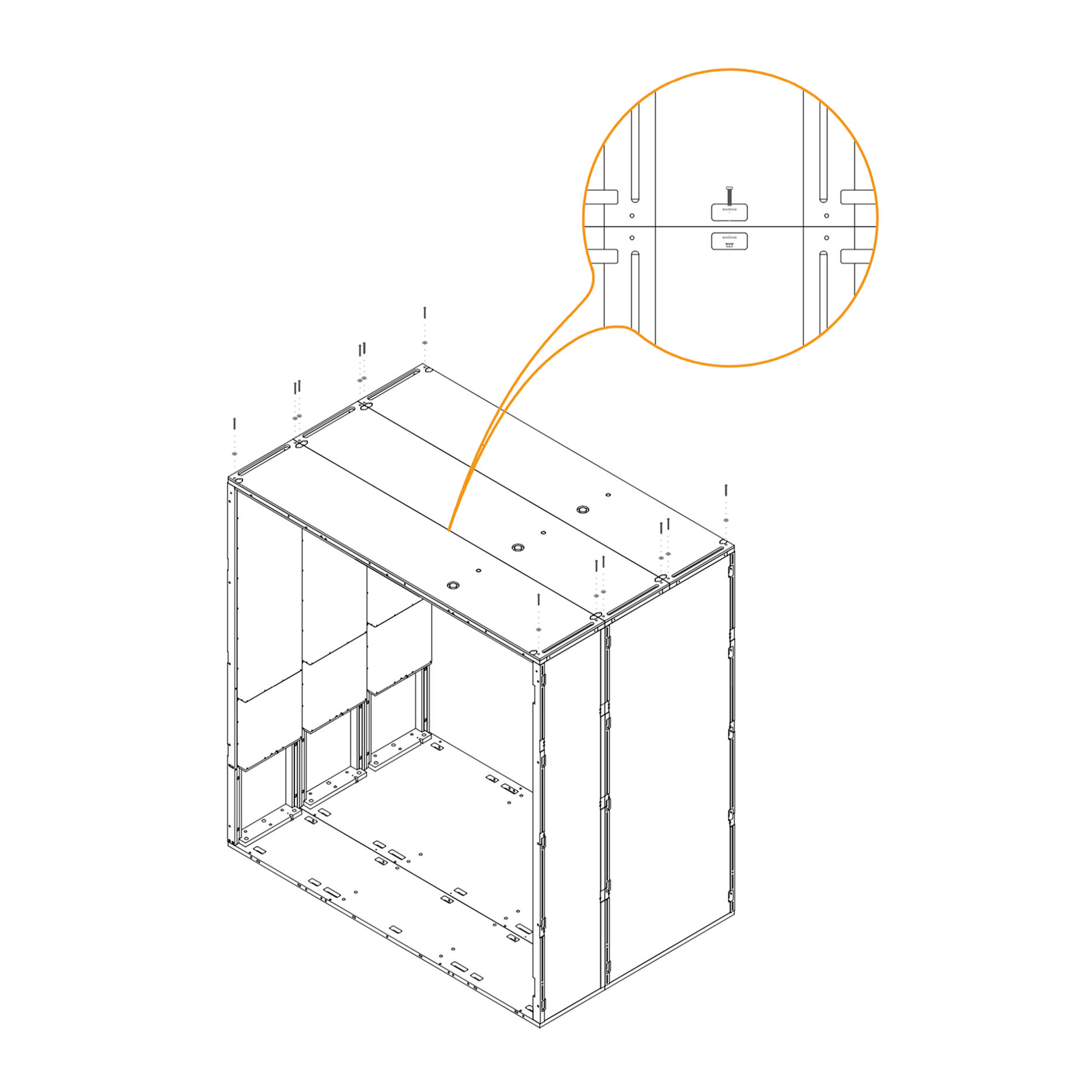
9. Secure Roof
Fasten the roof panel 4.1-FG4 to the structure using M6×60 mm flat head bolts (T0510).
Place a washer (T0198) under each bolt head.
Tighten all bolts to securely attach the roof panel.
Parts used:
roof panel | 4.1-FG4 | 1×
M6×60 mm flat head bolt | T0510 | 12×
washer 8.4×24×2.0 mm | T0198 | 12×
Rear Frame
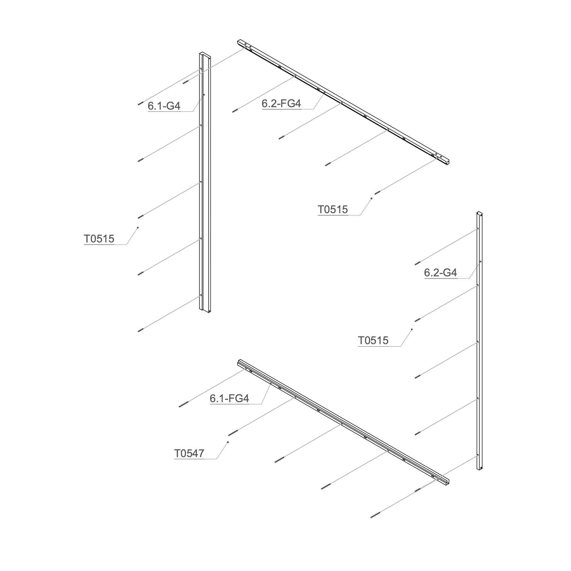
10. Attach Threaded Rod to Rear Frame
Place the M6×90 mm threaded rod (T0547) into the 6.1-FG4 and M6×50 mm threaded rod (T0515) into the 6.1-G4, 6.2-G4 and 6.2-FG4.
Parts used:
rear frame vertical profile | 6.1-G4 | 2×
rear frame horizontal beam | 6.2-FG4 | 2×
M6×50 mm bolt | T0515 | 15×
M6×90 mm bolt | T0547 | 5×
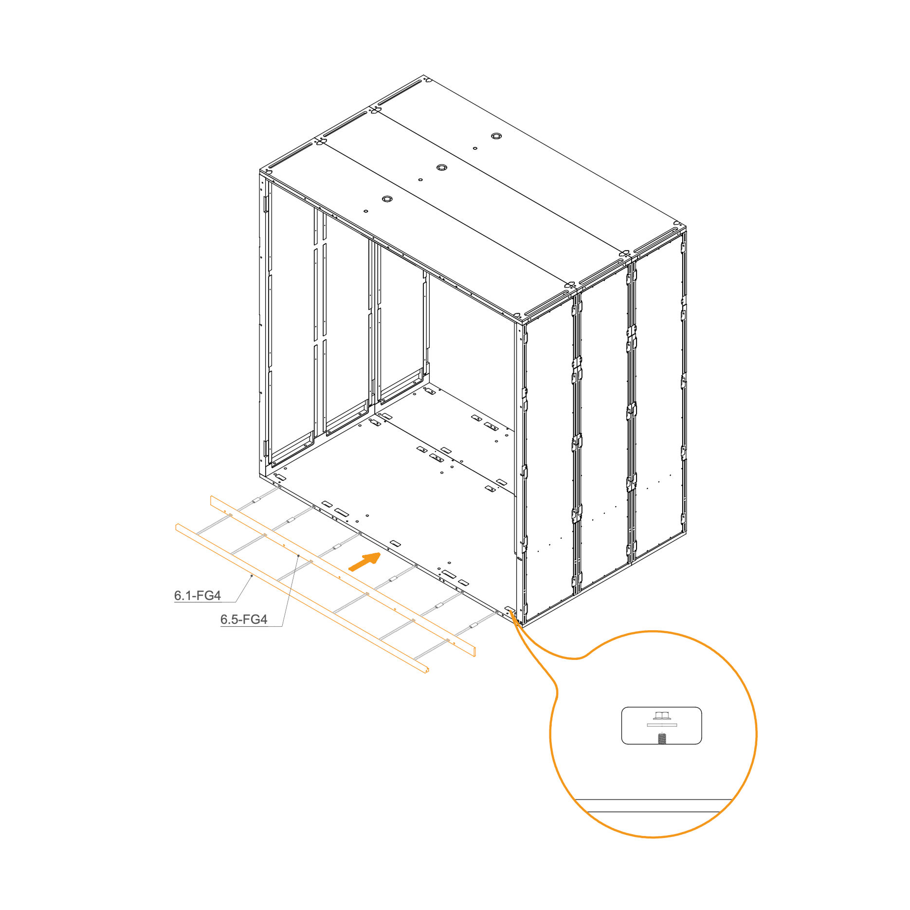
11. Attach Rear Frame to the Pod
Insert D8×50×22 mm dowels (T0536) into the oval holes
Align the horizontal frame 6.1-FG4 and 6.5-FG4 with the mounting slots at the rear edge of the floor panel.
Place washers (T0198) and M6 flange nuts (T0514) on the threaded rod in the floor cutouts.
Ensure the frame is aligned correctly before tightening properly.
Parts used:
rear floor beam | 6.5-FG4 | 1×
rear frame vertical profile | 6.1-FG4 | 1×
dowel pin D8×50×22 mm | T0536 | 6×
flange nut M6 | T0514 | 5×
washer 8.4×24×2.0 mm | T0198 | 5×
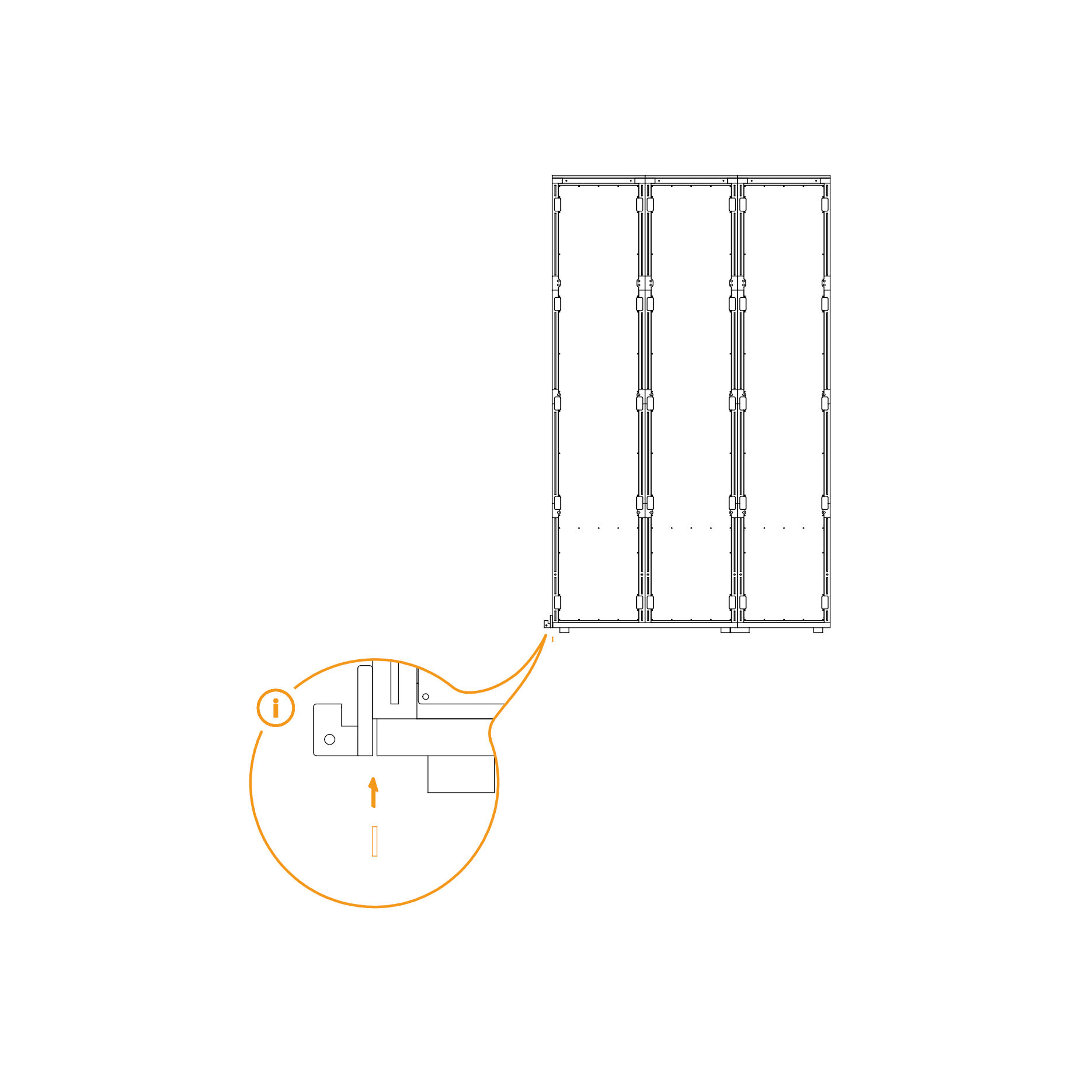
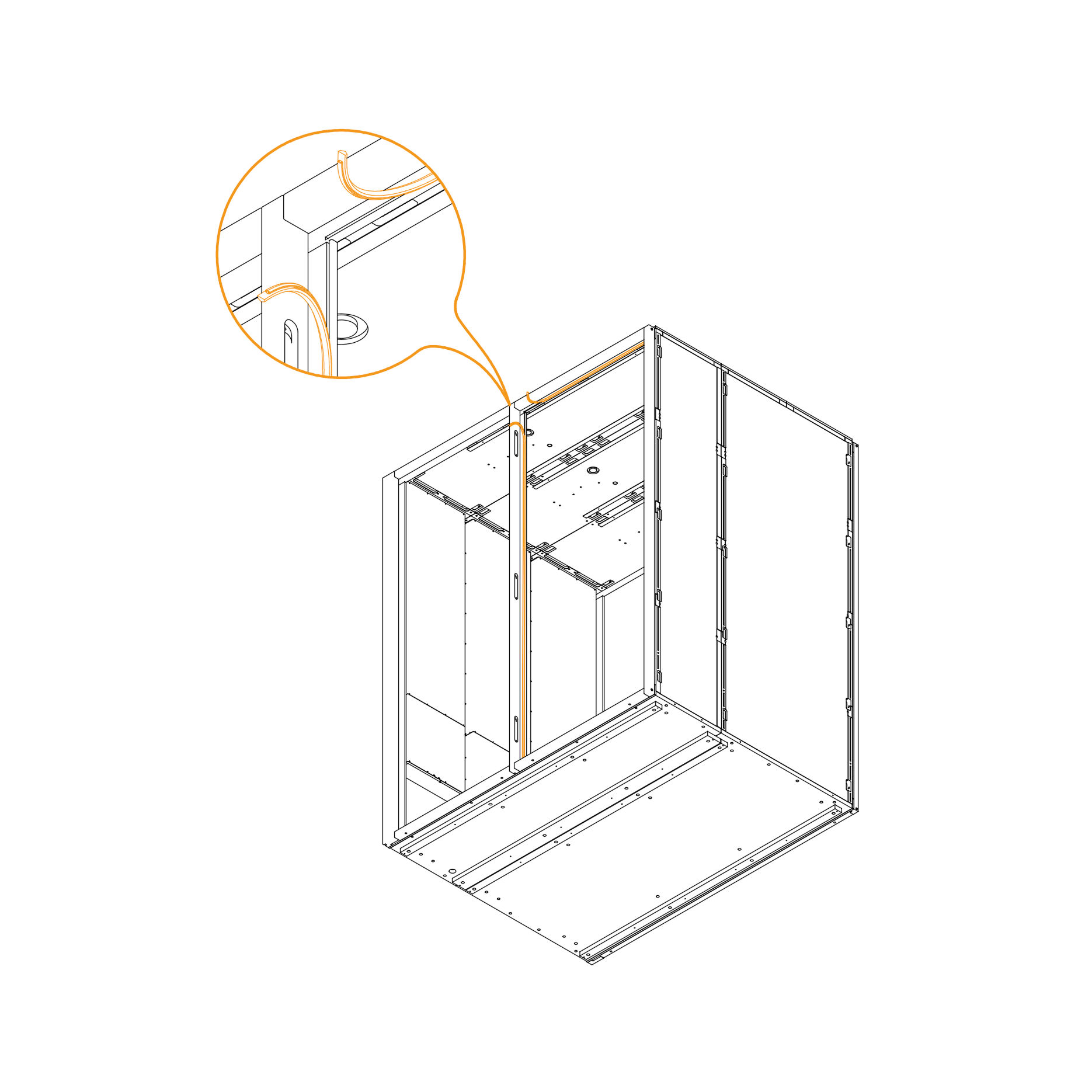
12. Check Gap and Insert Spacer if Necessary
If tIf there is a gap between the frame and the floor, insert a spacer into the groove as shown in the diagram.
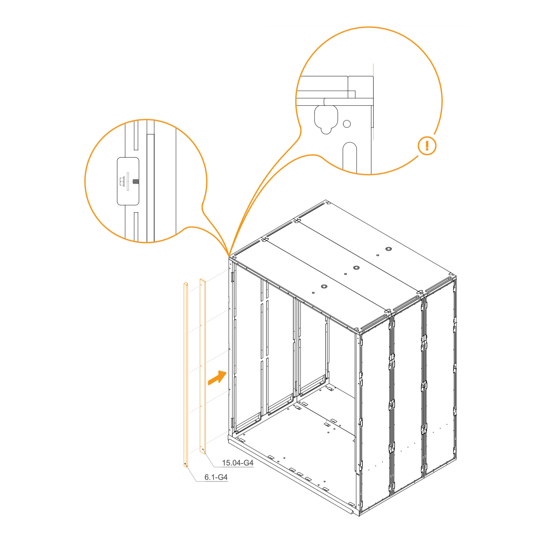
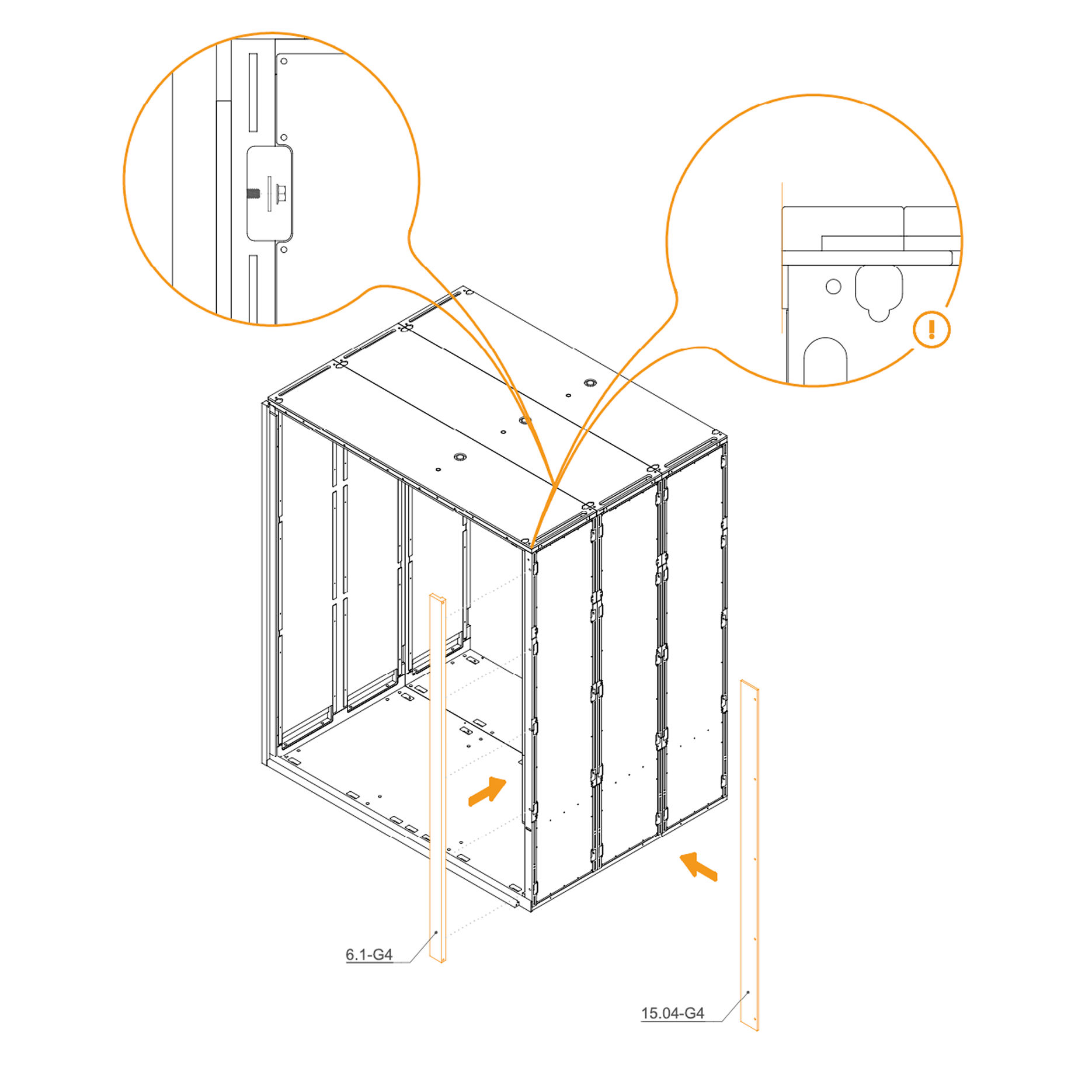
13. Attach Rear Frame to the Wall Panel
Place the two vertical frames, 6.1-G4 and 15.04-G4, in their designated positions.
Secure each frame by inserting a washer (T0198) and tightening an M6 flange nut (T0514) onto the threaded rod in the slot openings.
Ensure the frames are properly aligned before fully tightening the nuts.
Parts used:
rear vertical profile | 15.04-G4 | 1×
flange nut M6 | T0514 | 5×
washer 8.4×24×2.0 mm | T0198 | 5×
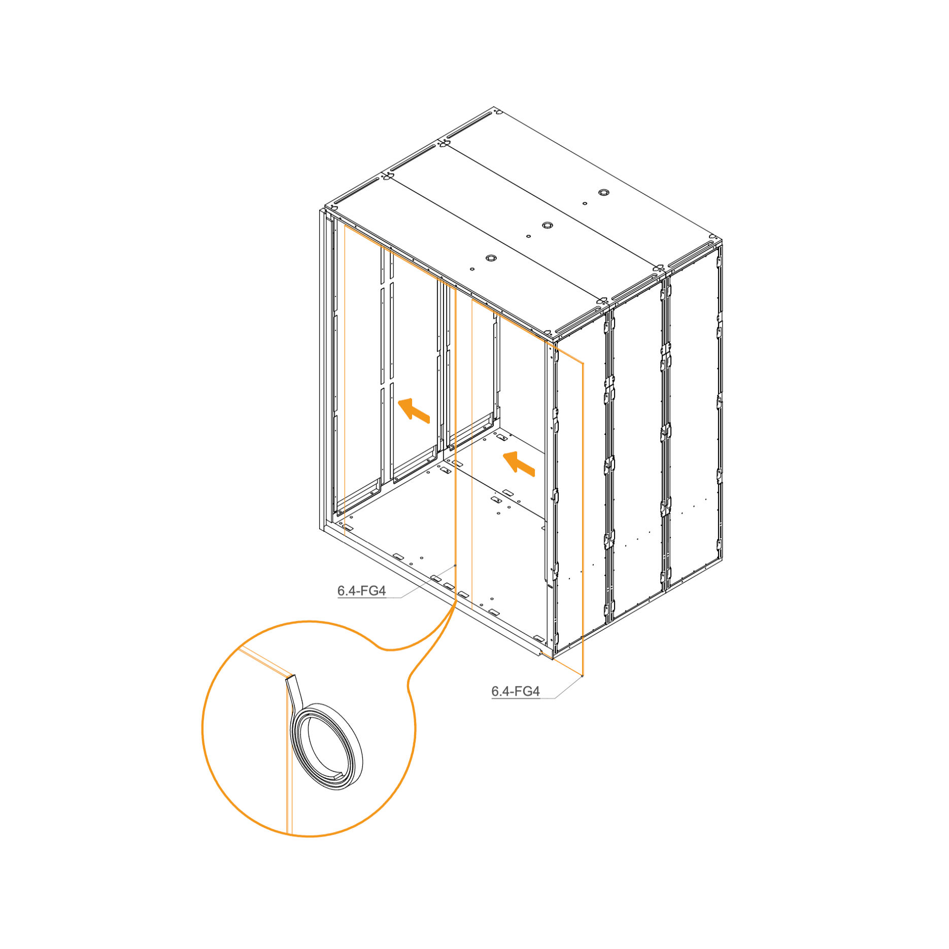
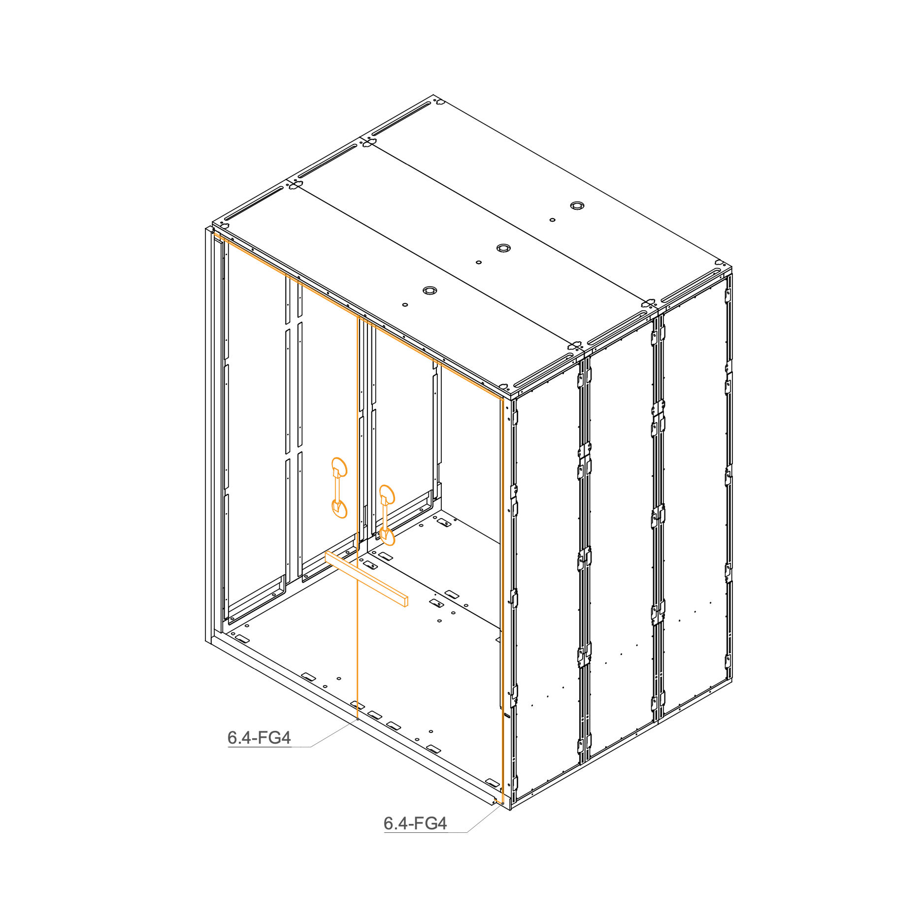
14. Install Rear Glass into the Frame
Clean the edge of the glass with the glass cleaner to remove any dust or grease.
Carefully apply double-sided gel tape along the cleaned edge. Do not remove the protective foil from the tape at this stage.
Insert the glasses 6.4-FG4 into the groove in the Rear frame.
Use suction cups to secure the second glass.
Parts used:
rear frame glass profile | 6.4-FG4 | 2×
15. Secure Glass Panels with Double-sided Tape
Align the glass with the groove on the side of the panel. Remove the protective film from the double-sided tape and use suction cups to pull the glass together.
Parts used:
rear glass panel | 6.4-FG4 | 2×
16. Attach Rear Frame to the Dock
Locate part 15.04-G4 (front right vertical profile) and 6.1-G4 (front left vertical profile).
Align each profile with the corresponding front frame posts.
Secure Rear frame using M6 flange nuts (T0514) and washers (T0198).
Parts used:
rear vertical profile | 15.04-G4 | 1×
rear frame profile | 6.1-G4 | 1×
flange nut M6 | T0514 | 5×
washer 8.4×24×2.0 mm | T0198 | 5×
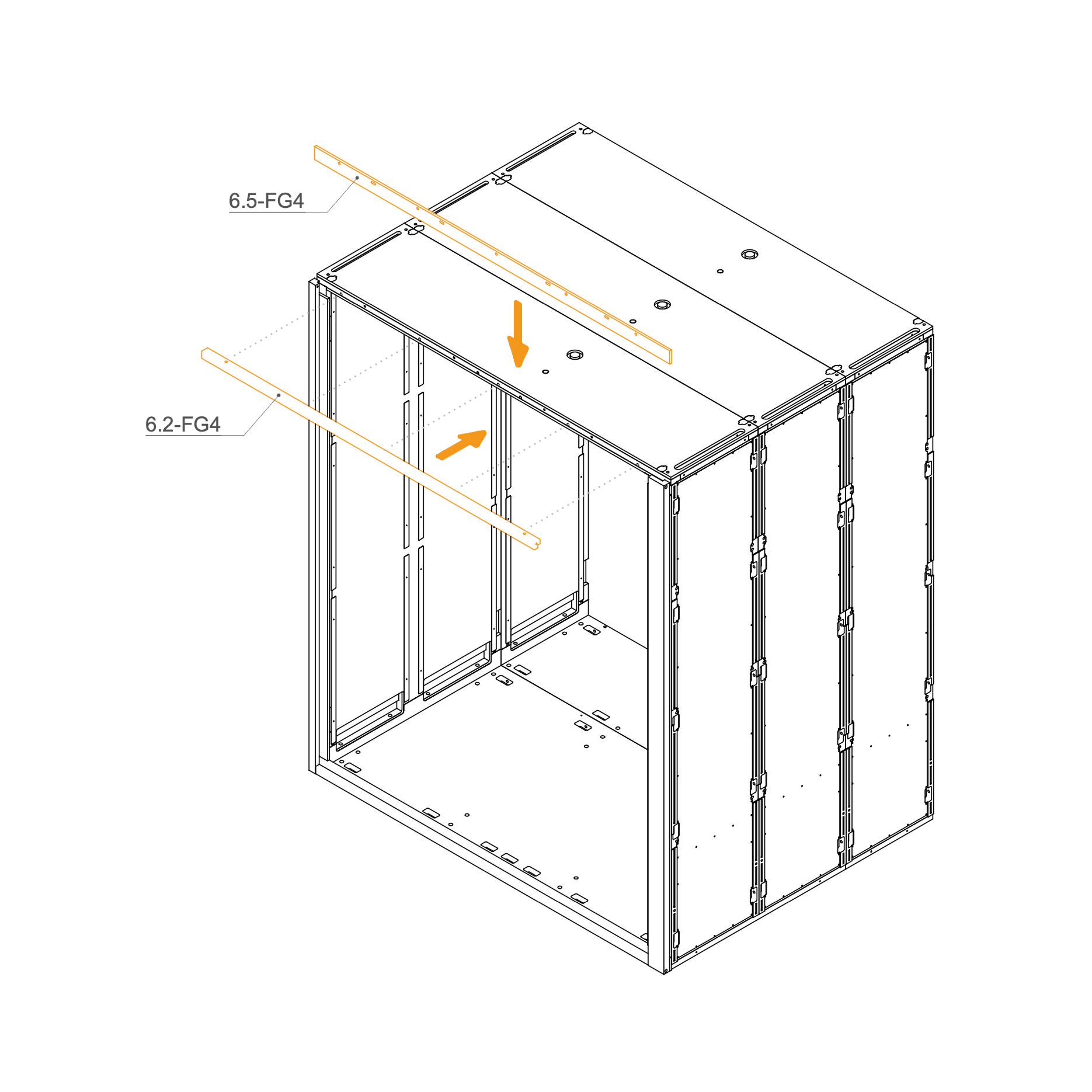
17. Attach Rear Frame to the Roof
Identify parts 6.2-FG4 and 6.5-FG4.
Place the frame at the top of the rear frame, aligning them with the corresponding holes.
Secure the profile using M6 flange nuts (T0514) and washers (T0198) as indicated.
Parts used:
horizontal profile | 6.2-FG4 | 1×
horizontal profile | 6.5-FG4 | 1×
flange nut M6 | T0514 | 5×
washer 8.4×24×2.0 mm | T0198 | 5×
Front Frame
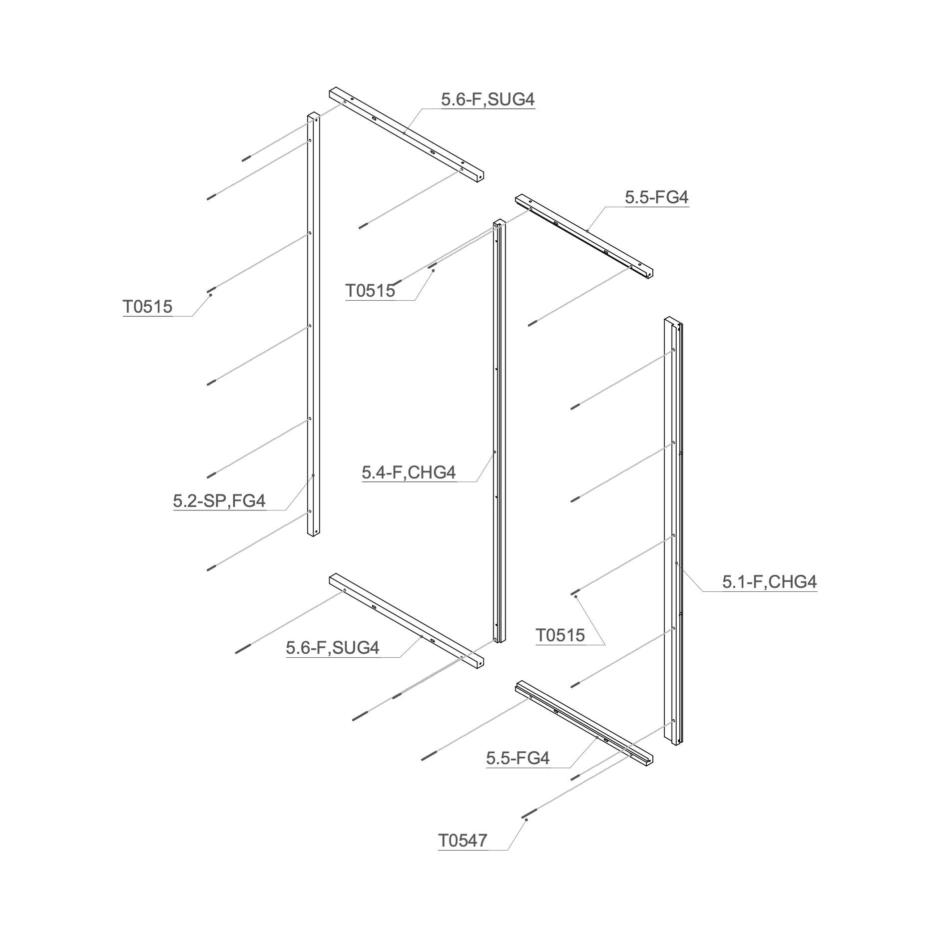
18. Attach the Threaded Rod to Front Frame
Place the M6×90 mm threaded rod (T0547) into 1x 5.5-FG4, 1x 5.6-F,SUG Frame.
Insert M6×50 mm threaded rod (T0515) into the 1x 5.2-SP,FG4, 1x 5.4-F,CHG4, 1x 5.1-F,CHG4 and 1x 5.5-FG4, 1x 5.6-F,SUG4 Frame.
Parts used:
M6x50 mm screw | T0515 | 21×
M6x90 mm screw | T0547 | 7×
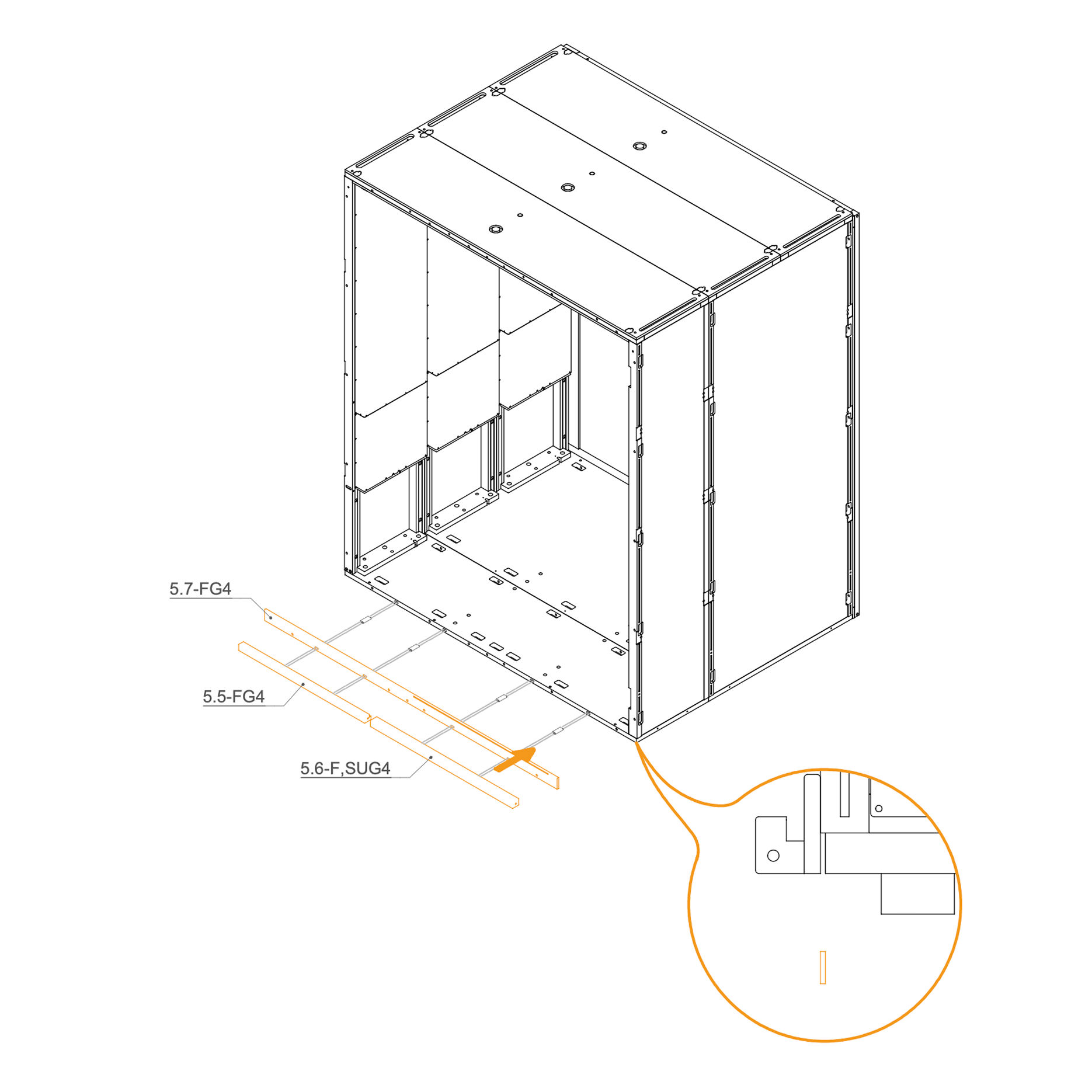
19. Attach Front Frame to the Floor Panel
Insert D8×50×22 mm dowels (T0536) into the oval holes
Align the horizontal frame 5.5-FG4 , 5.6-F,SUG4 and 5.7-FG4 with the mounting slots at the rear edge of the floor panel.
Place washers (T0198) and M6 flange nuts (T0514) on the threaded rod in the floor cutouts.
Ensure the frame is aligned correctly before tightening properly.
Parts used:
D8×50×22 mm spacer | T0536 | 6×
Flange nut M6 | T0514 | 7×
8.4×24×2.0 mm washer | T0198 | 7×
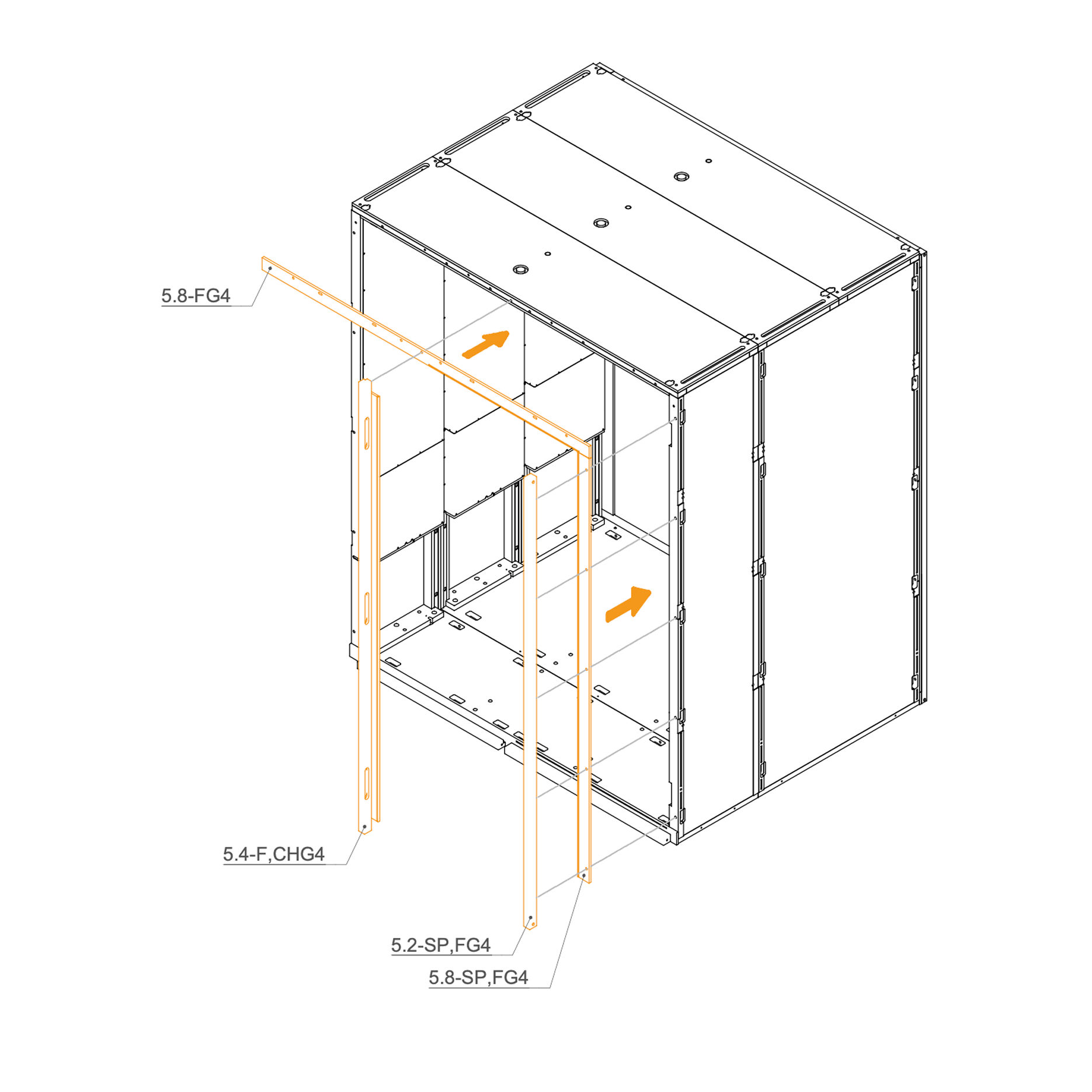
20. Attach Door and Roof Front Frame
Position the frame 5.2-SP,FG4, 5.8-SP,FG4,5.4-F,CHG4 and 5.8-FG4 at the front of the frame as shown.
Secure the profiles using flange nuts and washers from the hardware list.
Parts used:
Flange nut M6 | T0514 | 4×
8.4×24×2.0 mm washer | T0198 | 4×
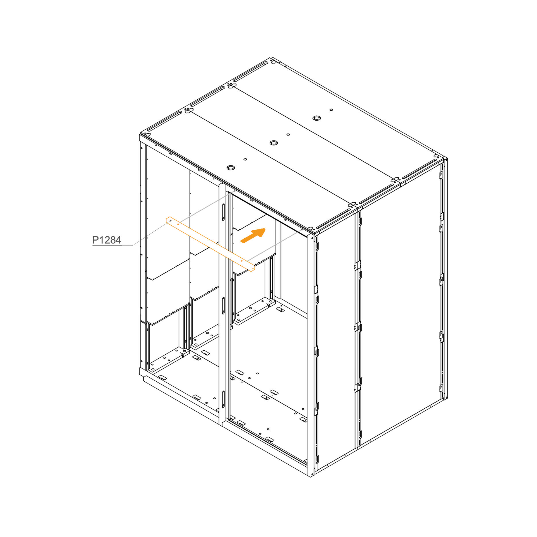
21. Attach Front Frame to the Roof
Insert the panel 5.5-FG4 horizontally between the two front frame uprights as shown.
Align the holes in the panel with the frame structure.
Secure in place using the specified hardware.
Parts used:
horizontal panel | P1284 | 1×
Flange nut M6 | T0514 | 3×
Washer 8.4×24×2.0 mm | T0198 | 3×
22. Install Rear Glass into the Frame
Insert glass panels 5.9-FG4 into the front frame groove.
Parts used:
glass | 5.9-FG4 | 1×
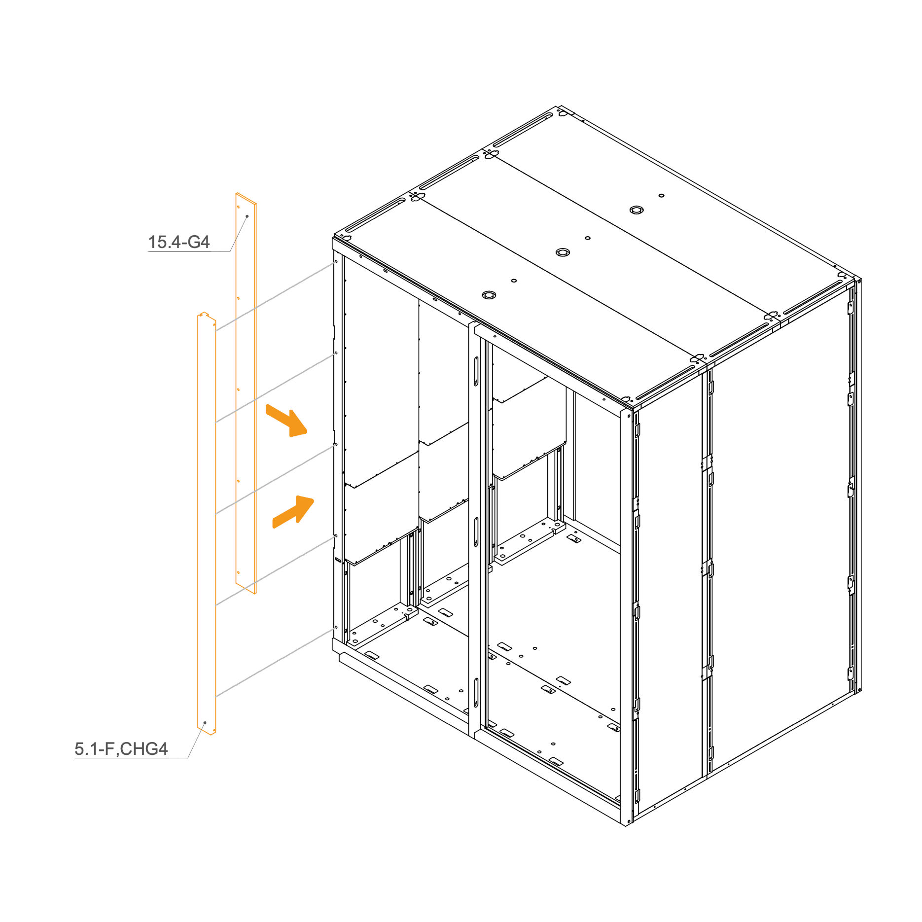
23. Attach Front Frame to Dock
Place the vertical frame 15.4-G4 and 5.1-F,CHG4 into their respective positions.
Secure the frame by inserting a washer (T0198) and tightening an M6 flange nut (T0514) onto the threaded rod in the slot openings.
Ensure the frame is properly aligned before fully tightening the nuts.
Parts used:
left vertical frame profile | 15.4-G4 | 1×
front corner profile | 5.1-F,CHG4 | 1×
flange nut M6 | T0514 | 10×
8,4×24×2,0 mm washer | T0198 | 10×
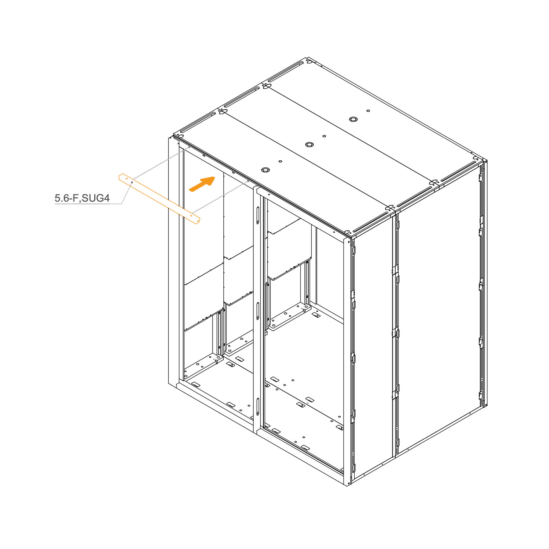
24. Attach Front Frame to the Roof
Insert 5.6-F,SUG4 horizontal frame, in its designated positions.
Secure each frame by inserting a washer (T0198) and tightening an M6 flange nut (T0514) onto the threaded rod in the slot openings.
Ensure the frames are properly aligned before fully tightening the nuts.
Parts used:
Flange nut M6 | T0514 | 4×
8,4×24×2,0 mm washer | T0198 | 4×
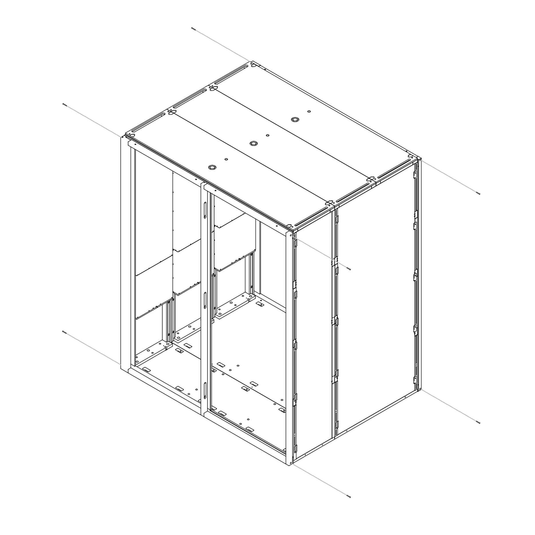
25. Secure the Rear frame and the Front frame
Insert M4×45 mm screws through the frame as shown to fasten the structure.
Parts used:
M4×45 mm screw | T0535 | 8×
Door
26. Install the Door Seal
Identify the vertical groove on the door frame along the closing edge.
Starting from the top, press the door seal into the groove, ensuring it seats firmly the entire length.
Continue pressing the seal down until it reaches the bottom, making sure there are no gaps or twists.
Check that the seal is straight and fully aligned to ensure proper closure and sound insulation.
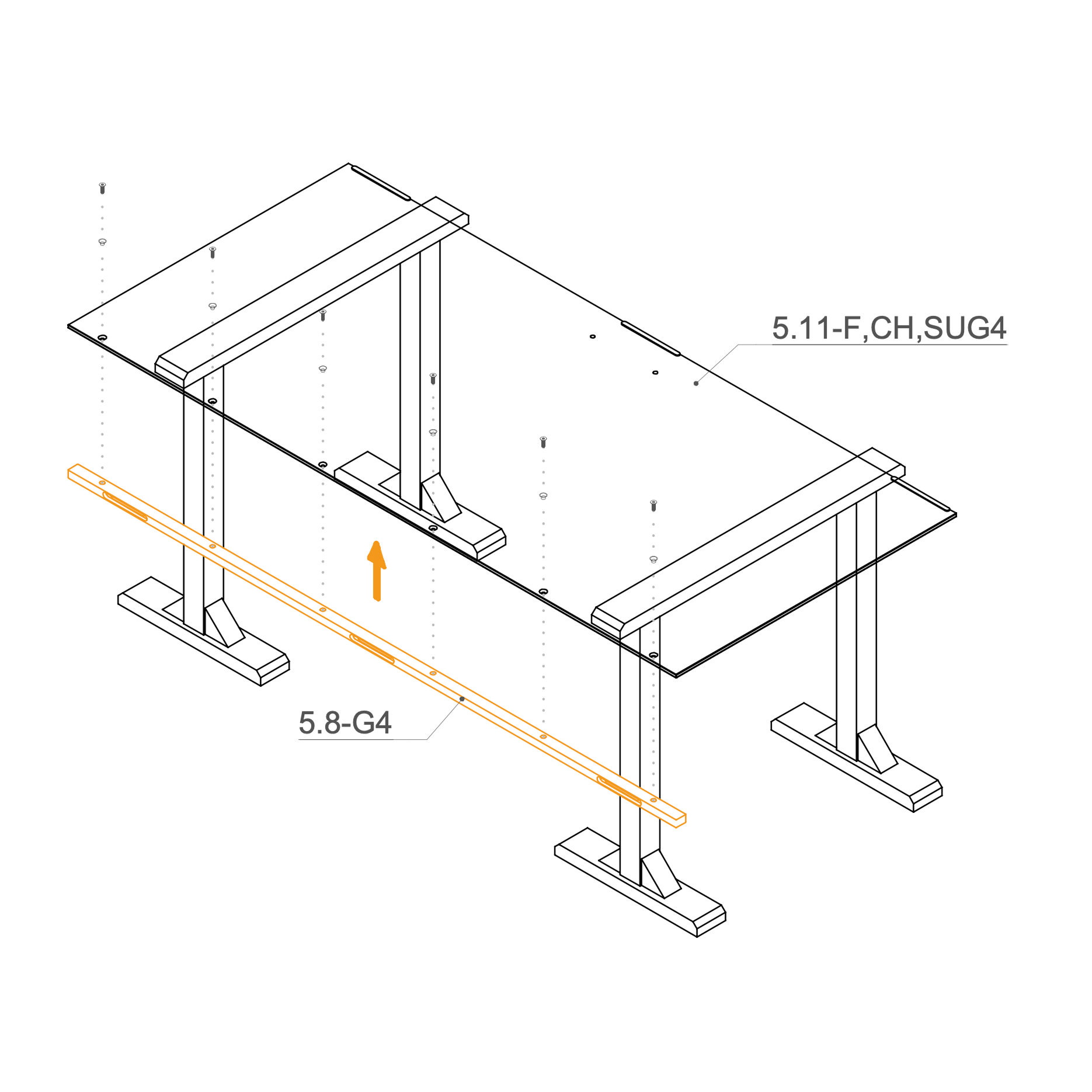
27. Fasten Frame to the Glass
Place the glass 5.11-F,CH,SUG4 on the working stand.
Insert the plastic insert (O0433) into the countersunk holes in the glass, and secure the frame to the glass using M8×25 mm screws (T0512).
Parts used:
M8×25 mm screw | T0512 | 6×
Insert | O0433 | 6×
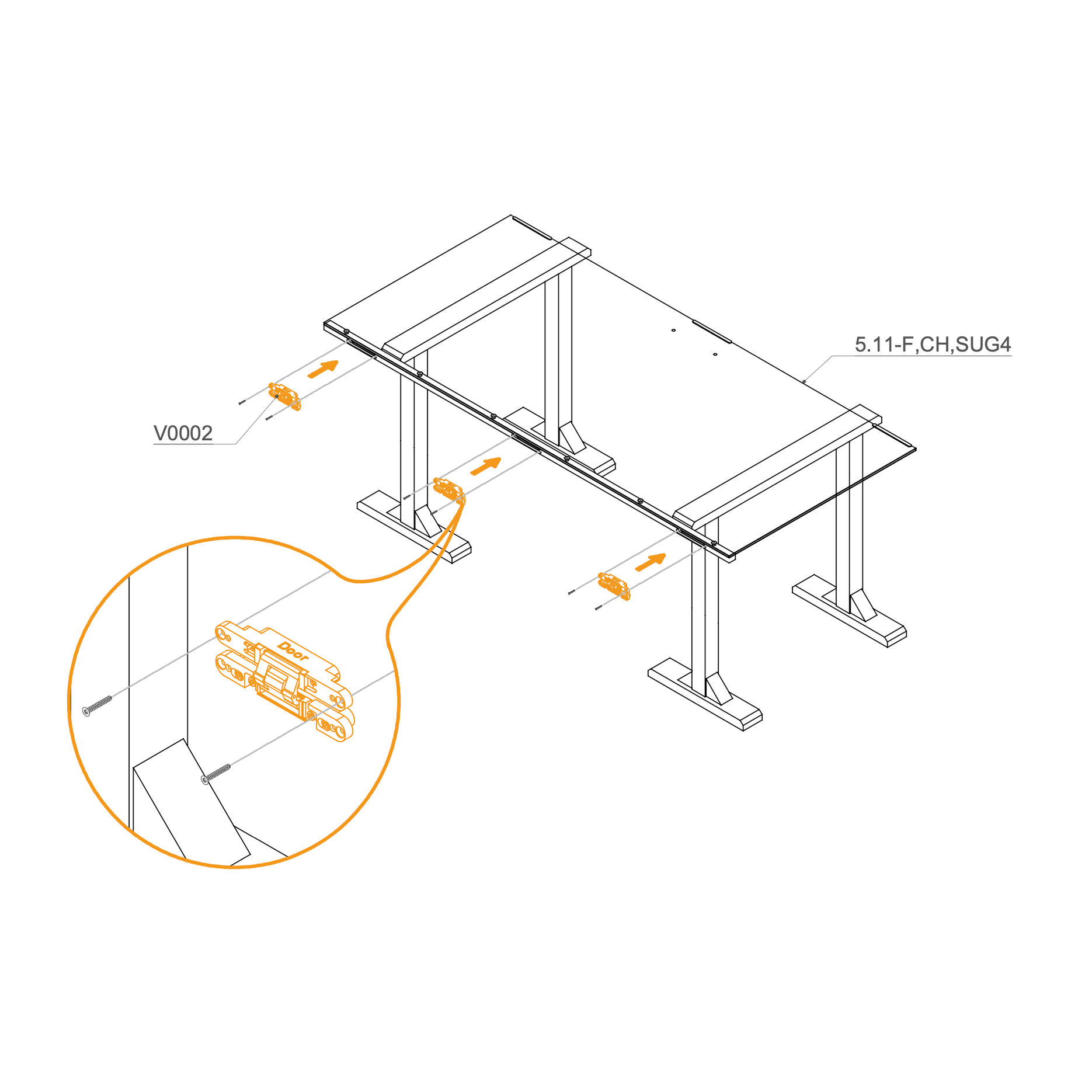
28. Mount Door Hinges
Attach hinges (V0002) into the recess use M4×30 mm screws to secure the position.
Repeat for all 3 positions as shown.
Parts used:
hinge | V0002 | 3×
M4×30 mm screw | T0070 | 6×
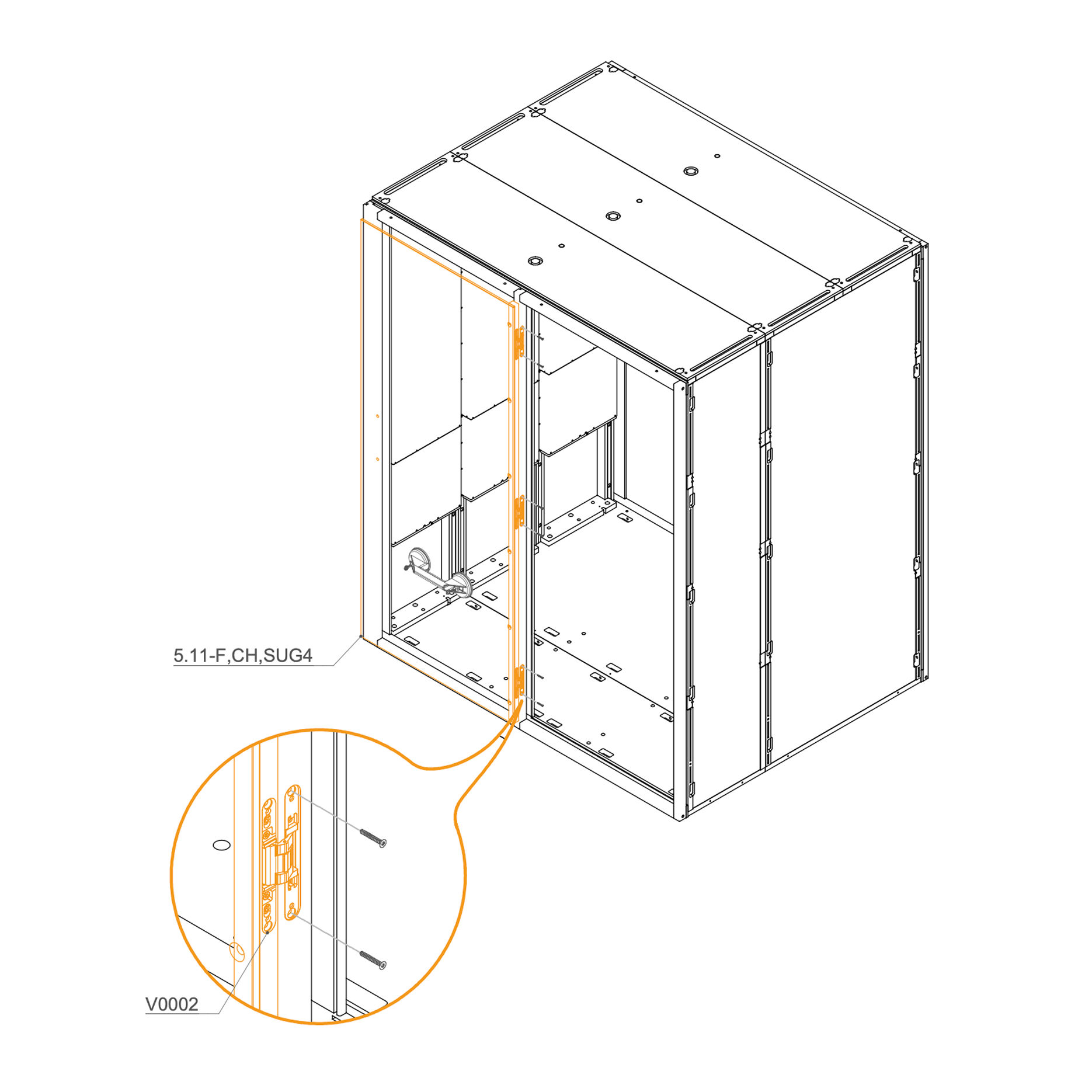
29. Secure the Door in the Frame
Place the door into the recesses in the frame and secure it with screws M4×30 mm (T0070).
Parts used:
M4×30 mm screw | T0070 | 6×
30. Install Handle
Align the two parts of the handle on either side of the hole in the glass.
Insert the enclosed M6×120 mm screw through the hole and fasten the handle parts using a 4 mm hex key.
Place the plastic spacer between the screw and the glass to prevent direct contact.
Tighten the screw securely, ensuring the handle is firmly attached without over-tightening.
Parts used:
M6×120 mm bolt | T0530 | 2×
6.2×10×10 mm spacer | T0097 | 2×
Speakers
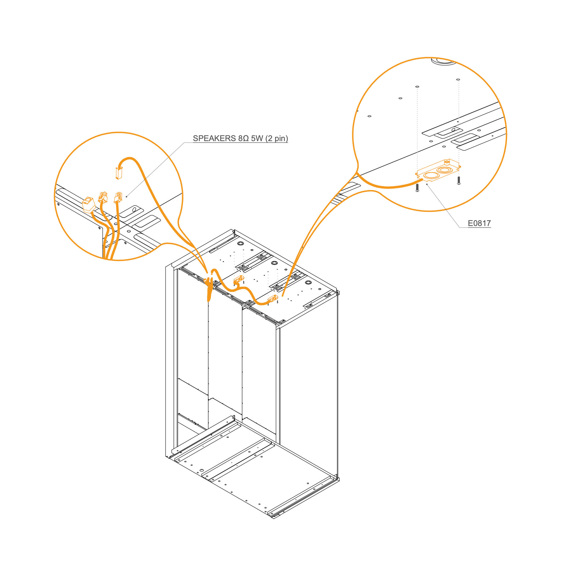
31. Install Speakers
Connect the PIR sensor cable (RJ11) and the dual light cable (6 pin).
Position and secure the light panel to the ceiling using screws.
Parts used:
M4×10 mm screw | T0499 | 4×
Light
32. Install Light
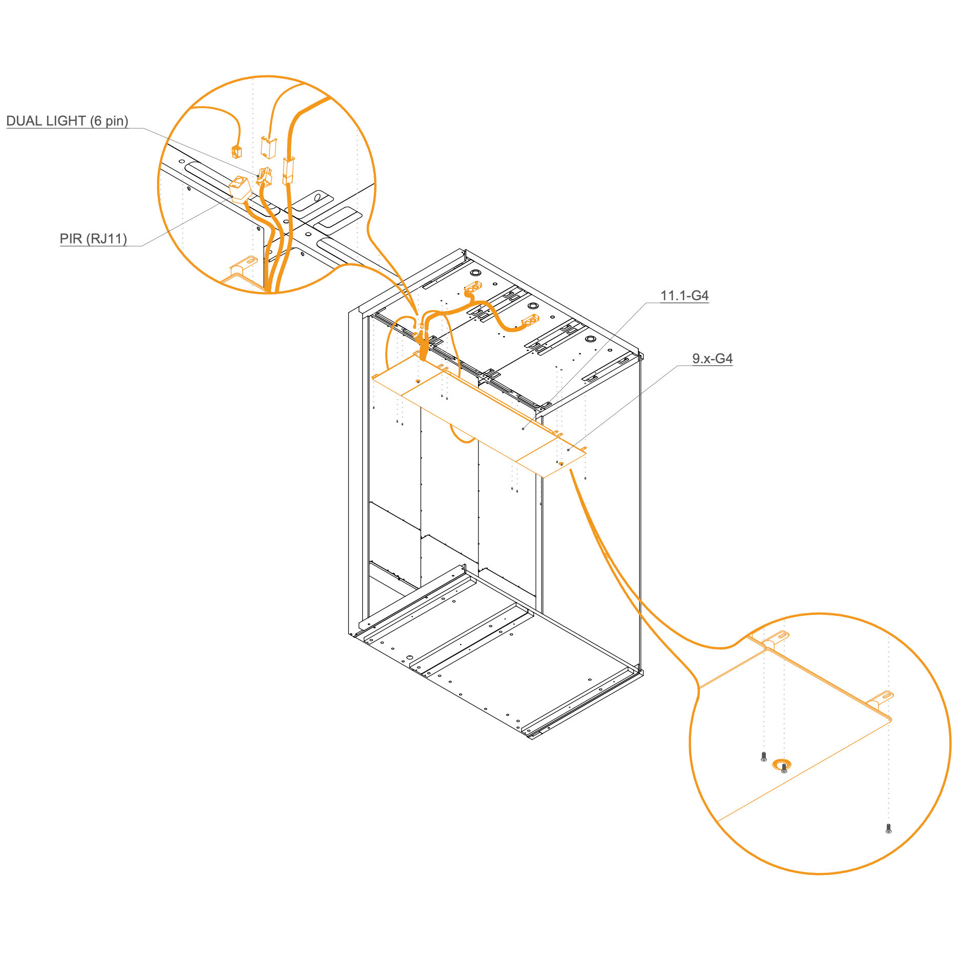
Connect the DUAL LIGHT (6 pin) cable to its connector in the ceiling panel.
Connect the PIR sensor (RJ11) cable to the control box.
Place the light module (11.1-G4) and PIR sensor module (9.x-G4) into their designated cutouts in the ceiling.
Fasten the modules in place using the provided screws.
Parts used:
M4×10 mm screw | T0499 | 4×
Electro Connection
33. Complete Electrical Wiring
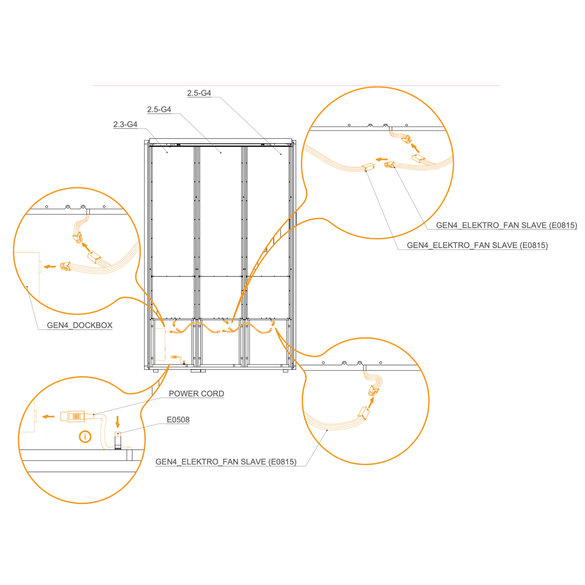
Connect all GEN4_ELEKTRO_FAN_SLAVE (E0815) cables as shown in the diagram.
Attach the cables from the GEN4_DOCKBOX to their respective connectors.
Insert the power cord (E0508) into the power socket.
Plug in the power cord, test the electrical connections, then unplug the cord once testing is complete.
Parts used:
Power cord | E0508 | 1×
External Panels
34. Attach Eternal Panels
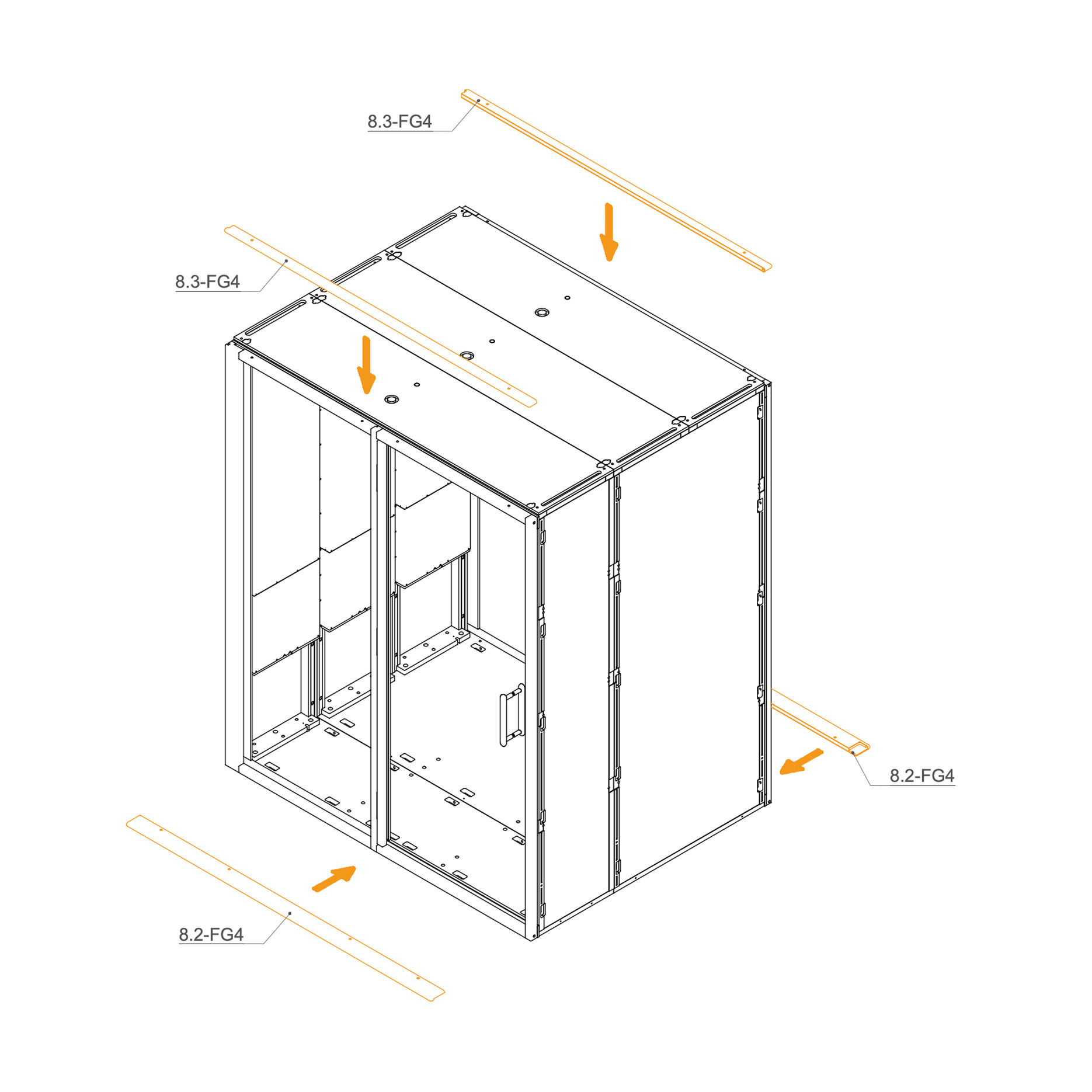
Install the upper panels 8.3-SUG4 by aligning them with the edge of the frame and the screw holes.
Prepare the lower panels 8.2-SUG4 by positioning them underneath the frame. You may use spacers or supports to make fastening easier.
Parts used:
external panel | 8.3-FG4 | 2×
external panel | 8.2-FG4 | 2×
35. Fix the External Panels
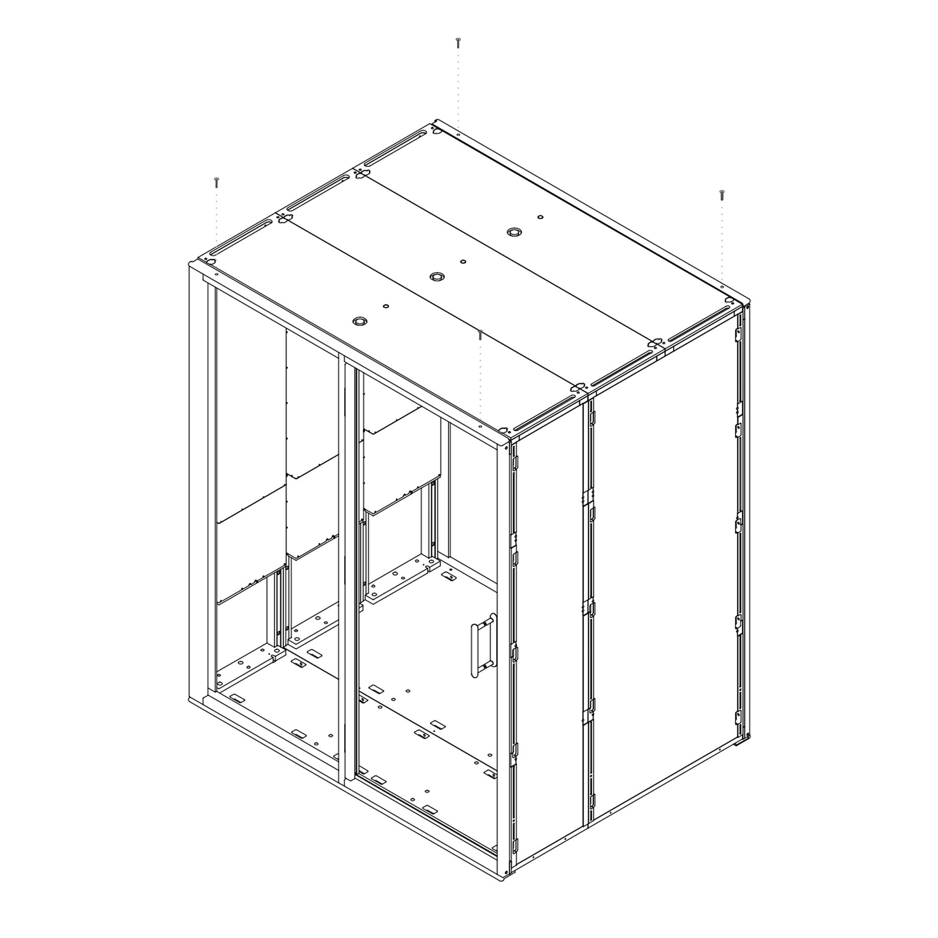
Secure the previously placed external panels using screws (T0397).
Parts used:
M6x40 mm bolt | T0397 | 12×
Ledge
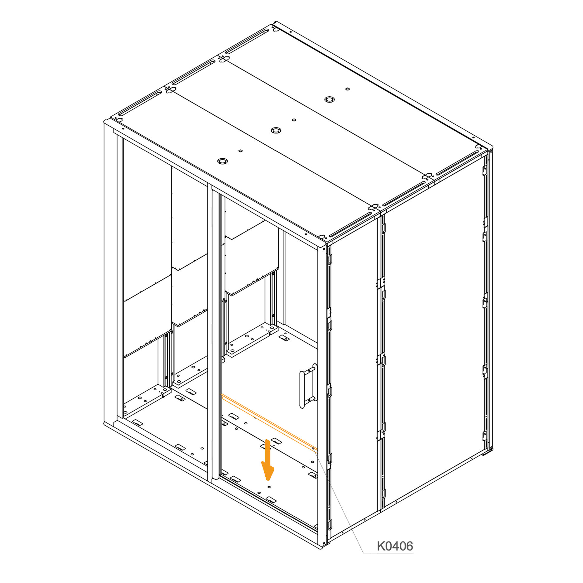
36. Install Ledge
Apply double-sided tape along the back of the ledge (K0406).
Stick the ledge to the indicated position on the frame.
Parts used:
ledge | K0406 | 1×
Floor Isolation
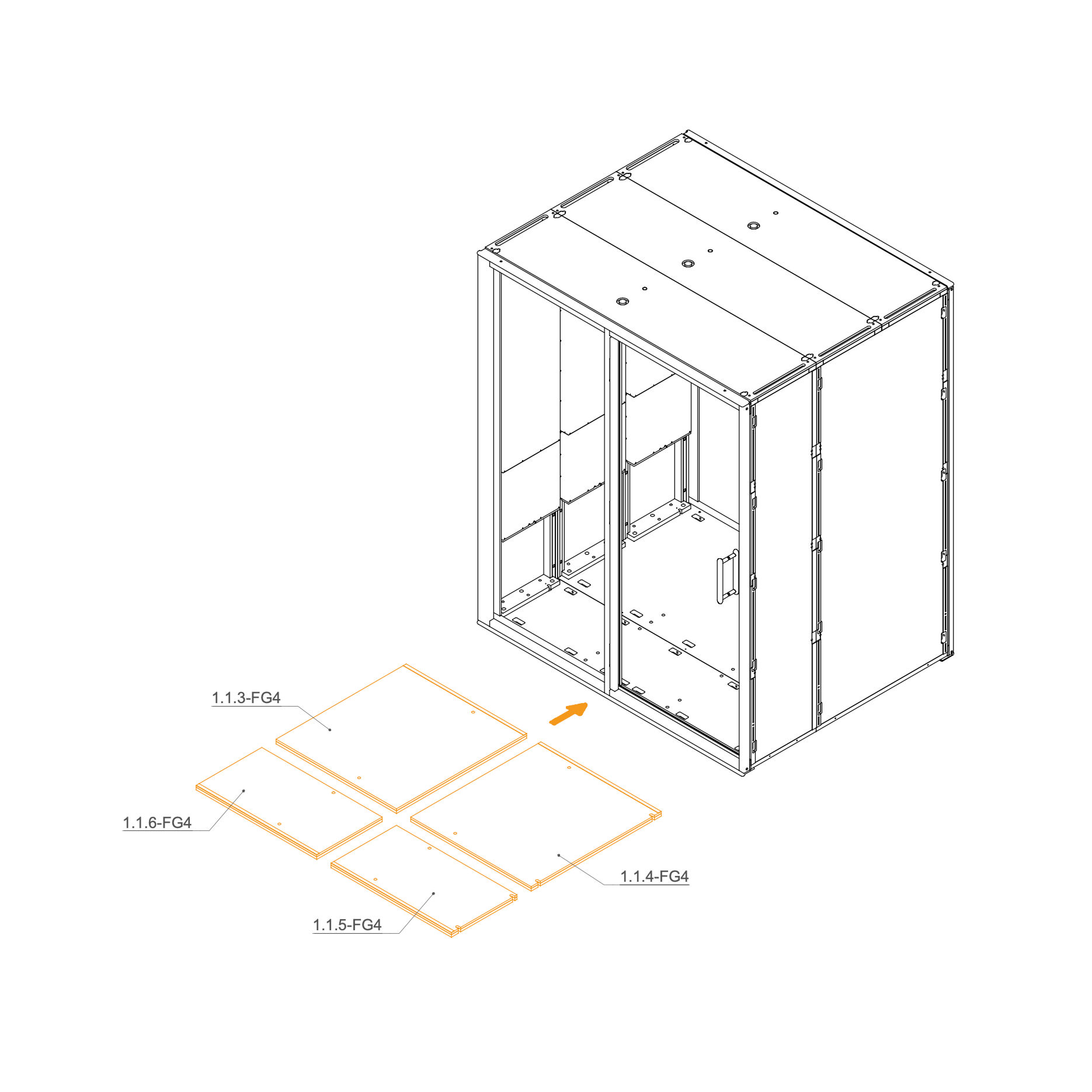
37. Place Floor Isolation Panels inside the Pod
Place the floor insulation panels inside the pod as shown.
Ensure correct placement: panels marked 1.1.3-FG4, 1.1.4-FG4, 1.1.5-FG4, 1.1.6-FG4 panels cover the right and center sections.
Carpet
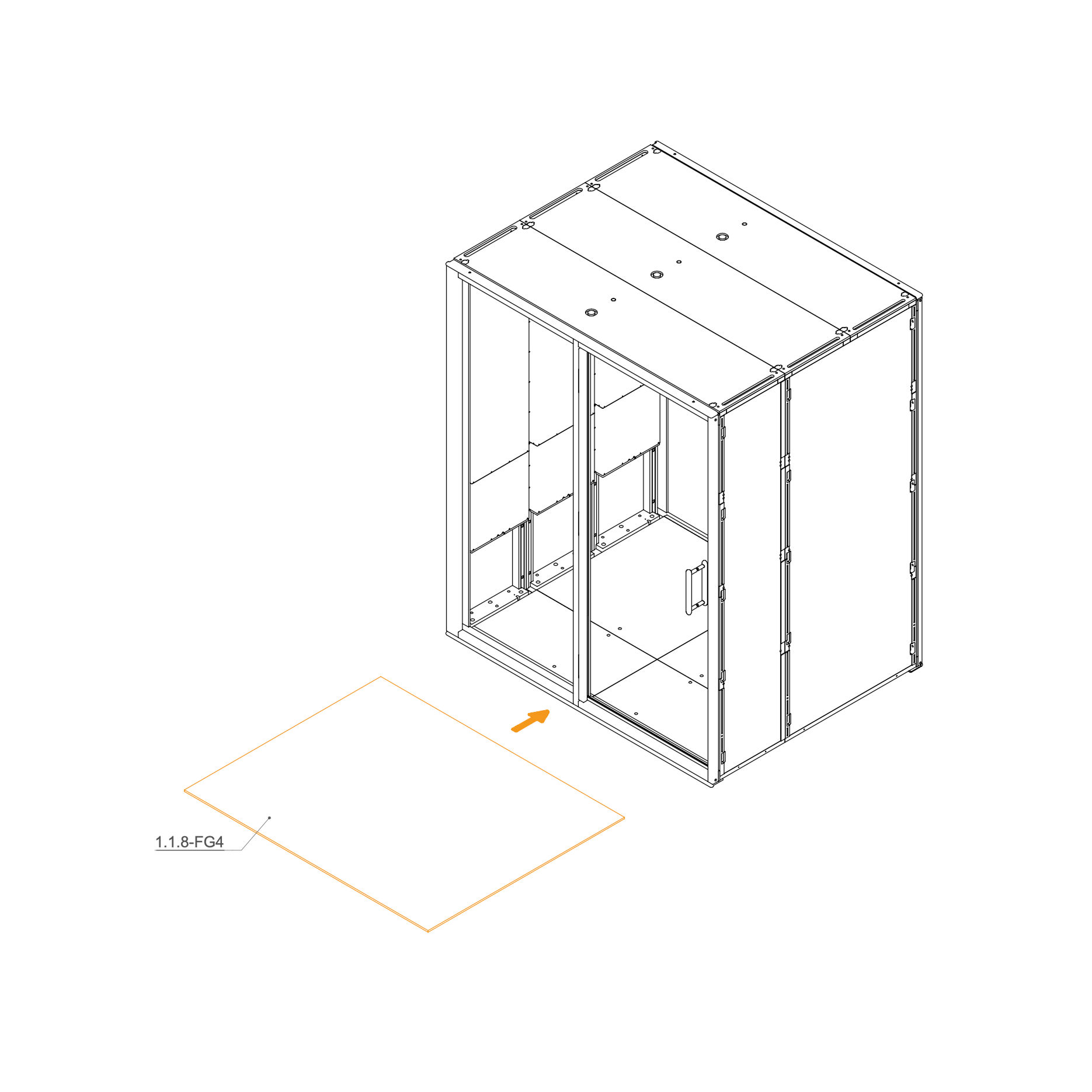
38. Lay Carpet on the Floor
Place the carpet (1.1.8-FG4) onto the floor panels inside the booth.
According to the perforations in the carpet, cut holes where needed, depending on the planned position of the table.
Parts used:
carpet | 1.1.8-FG4 | 1×
Occupancy Light Cable
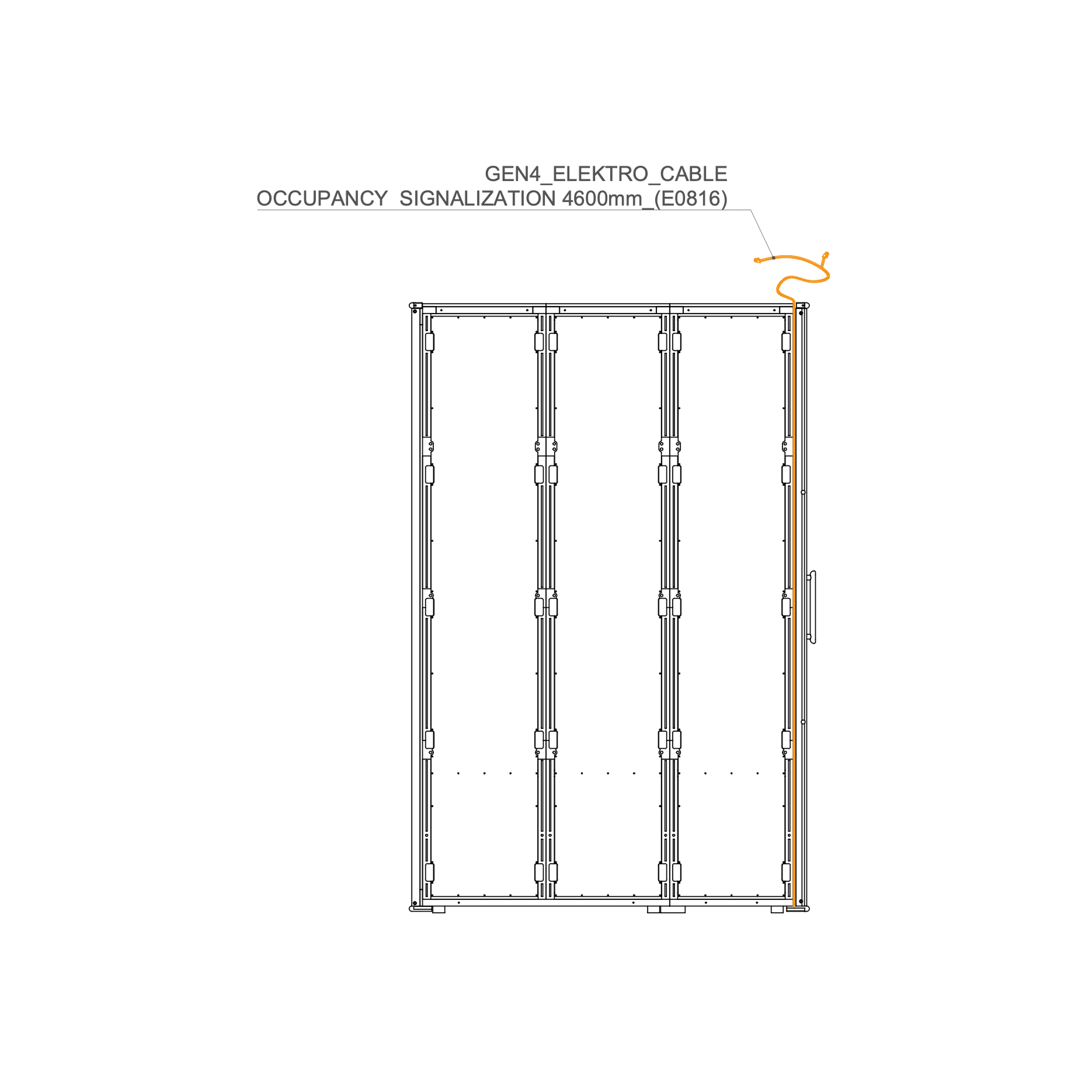
39. Route the Occupancy Light Cable through the Frame
Route the GEN4_ELEKTRO_CABLE OCCUPANCY SIGNALIZATION 4600mm (E0816) along the indicated path inside the booth, positioning it as shown in the diagram.
Parts used:
occupancy signalization cable 4600 mm | E0816 | 1×
Interior Panel
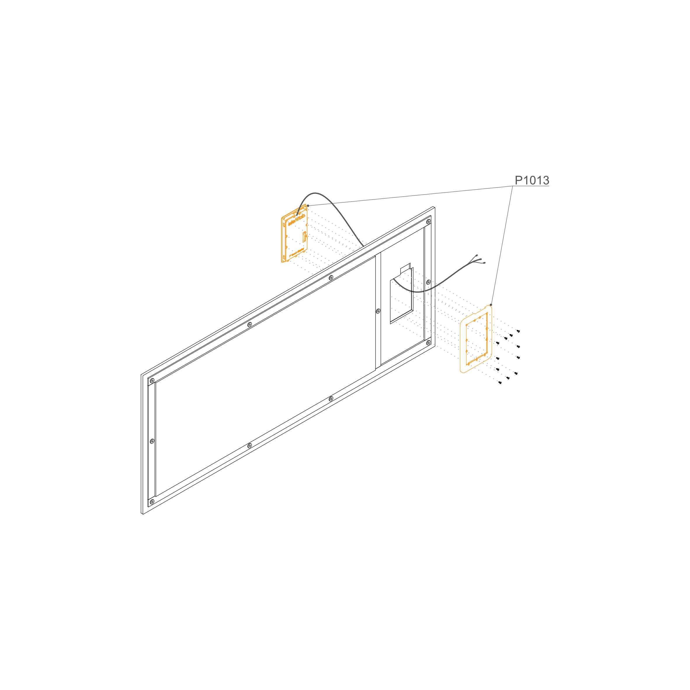
40. Insert Display into the Interior Panel
Unpack the Components: Carefully open the packaging and identify the display unit (P1013)
Disassemble the Housing: Using a screwdriver with a Torx bit, remove the rear frame from the display unit to prepare it for mounting.
Feed the Cables: Locate the cutout in the upholstered internal panel. Gently pull all display cables through the hole from the front (upholstered side) to the back.
Note: Ensure the cables are oriented upwards as shown in the diagram.
Seat the Display: Insert the display unit into the cutout on the upholstered side of the panel until it sits flush against the surface.
Mount the Rear Frame: From the back of the panel, align the rear frame (P1013) with the back of the display unit.
Fasten the Bolts: Insert the provided bolts through the frame and into the display housing. Tighten them securely to sandwich the upholstered panel between the display and the rear frame.
Note: The upholstered panel shown is for illustration only. Additional holes may be present to accommodate potential socket installations.
Parts used:
Interior panel | 7.3-F,CH4G4 | 1×
Display | P1013 | 1×
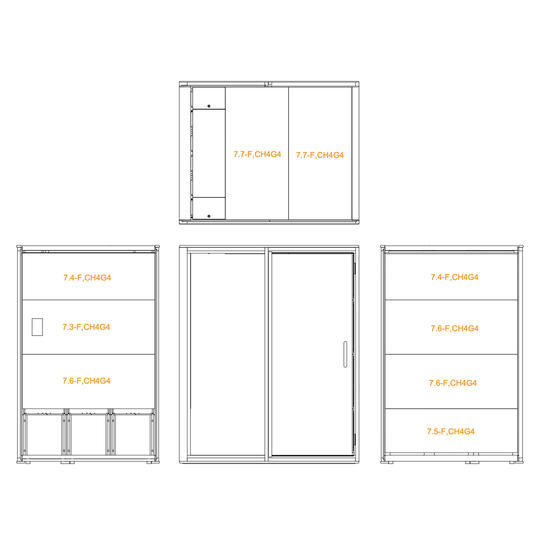
41. Install Interior Wall and Ceiling Panels
Position each interior panel according to the diagram, matching the panel code to its designated location.
Install panel 7.3-F,CH4G4 in the central slot with the cutout for the accessory frame.
Install panel 7.4-F,CH4G4 above and below the central panel as shown.
Install panels 7.5-F,CH4G4, 7.6-F,CH4G4, and 7.7-F,CH4G4 in their respective positions according to the diagram.
Ensure all panels are flush and properly aligned before securing.
Exterior Panels
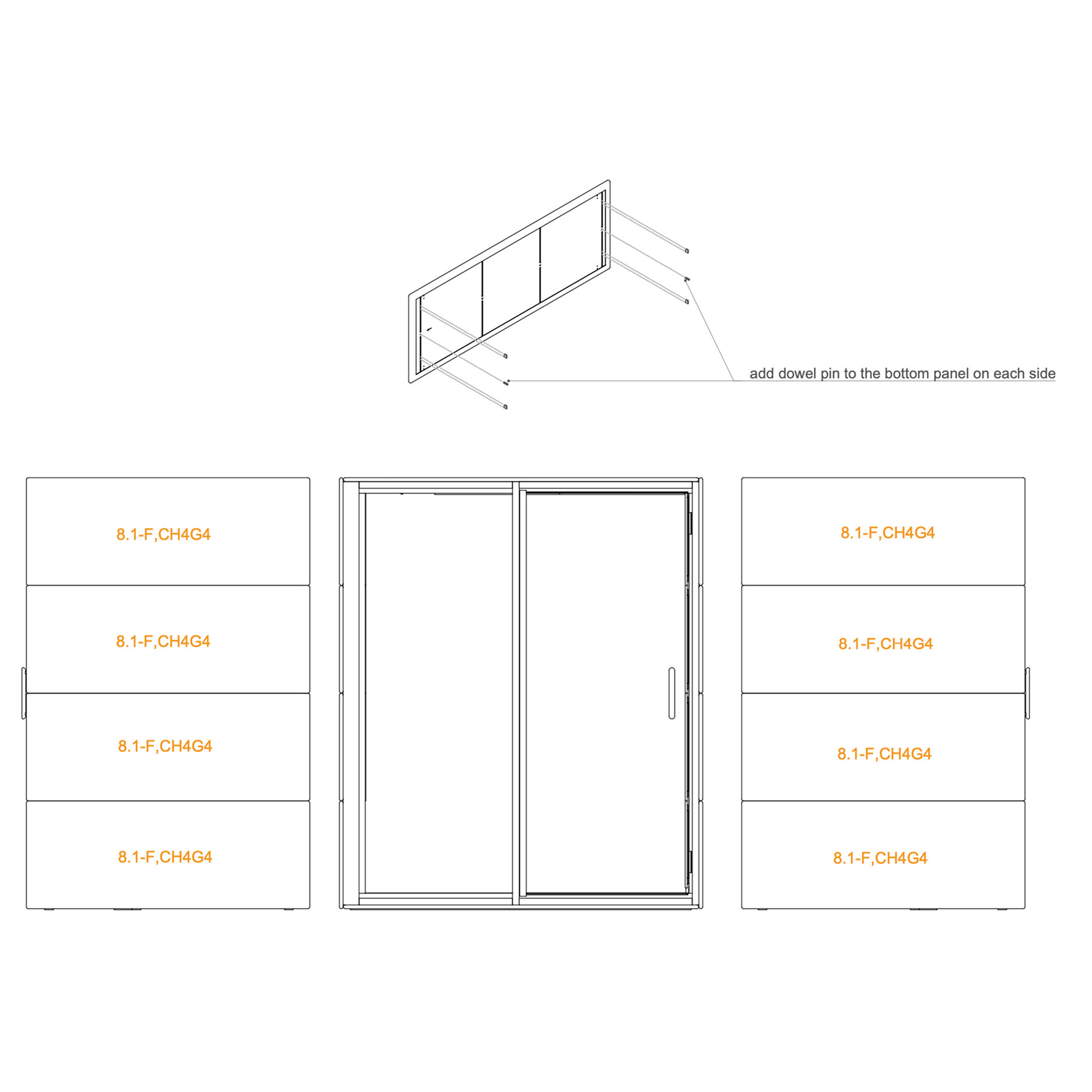
42. Install External panels
Position the exterior panels 8.1-F,CH4G4 on both sides of the booth, as shown in the diagram.
Before installing, add at least four clip connectors to one external panel as indicated.
Insert a dowel pin into the bottom panel on each side for proper alignment.
Carefully align each panel and press into place.
Parts used:
exterior panel | 8.1-F,CH4G4 | 8×
Occupancy Light
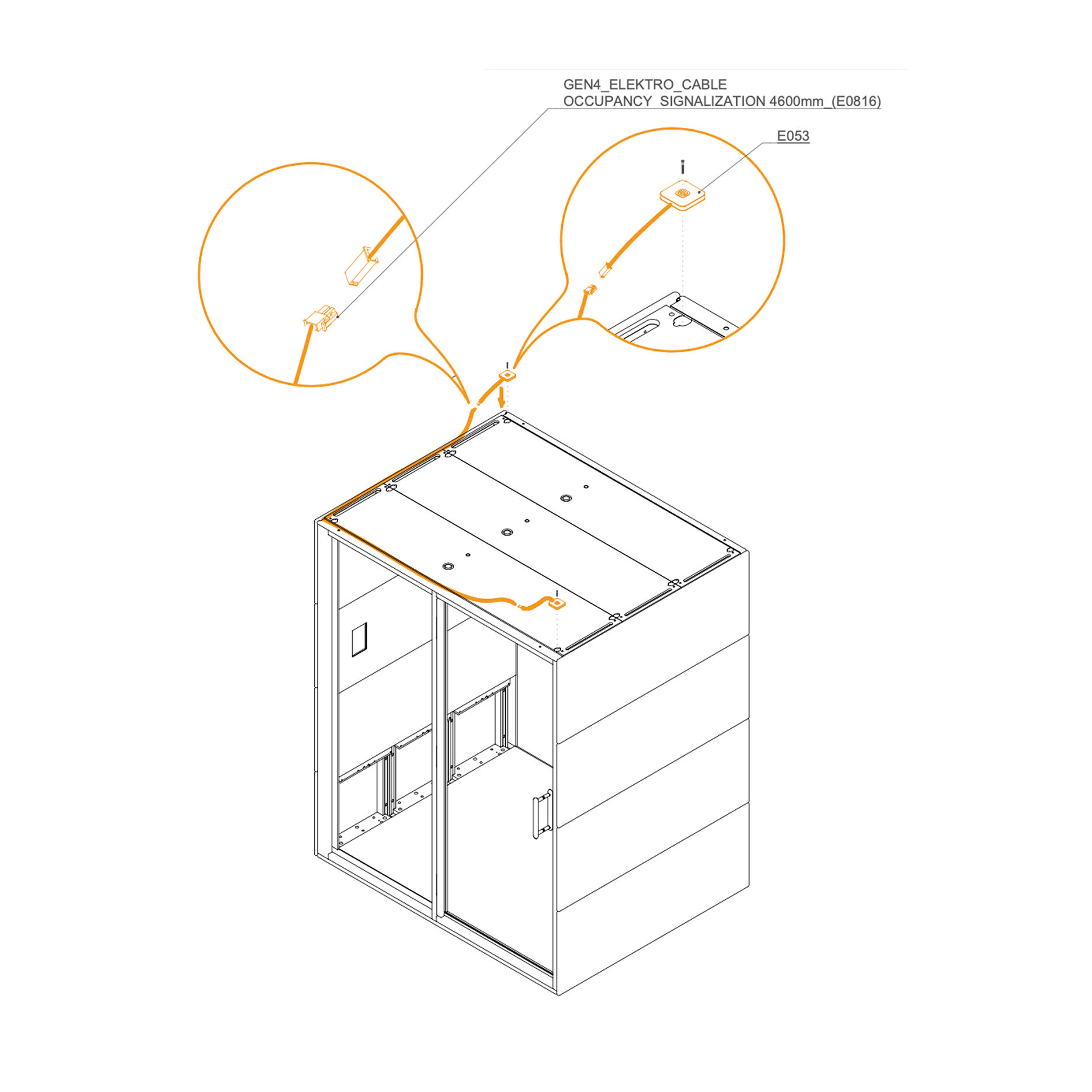
43. Install Occupancy Light
Route the GEN4_ELEKTRO_CABLE OCCUPANCY SIGNALIZATION 4600 mm (E0816) as shown.
Connect the cable to the occupancy light.
Secure the occupancy light (E053) to the frame with the provided screws.
Parts used:
occupancy light | E053 | 2×
3×30 mm screw | T0136 | 2×
Door
44. Adjust the door
Check the door adjustment in the video.
Hinge Covers
45. Install Hinge Cover
Place the hinge covers over the hinges on the door frame as shown.
Secure each cover with screws
Parts used:
hinge cover | not labeled | 6×
M4×10 mm screw | T0310 | 12×
Ledge
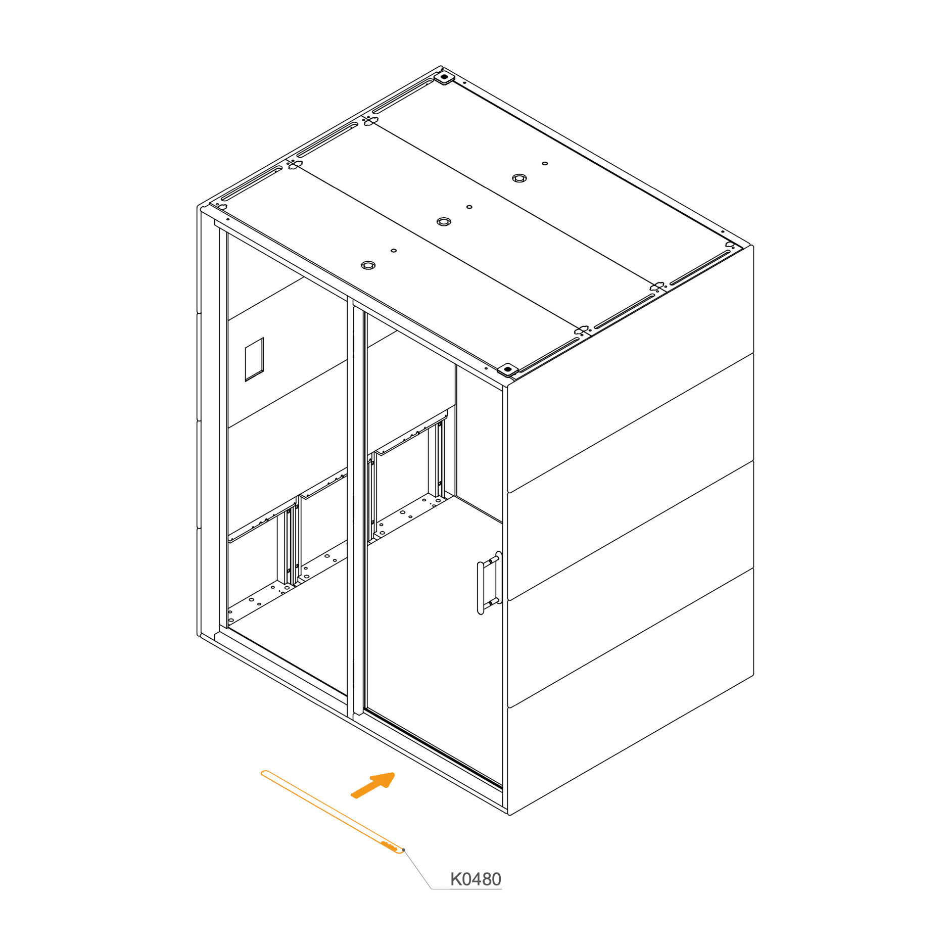
46. Install Ledge
Place the hinge covers over the hinges on the door frame as shown.
Secure each cover with screws
Parts used:
ledge | K0480 | 1×
double-sided tape
Cord Connection
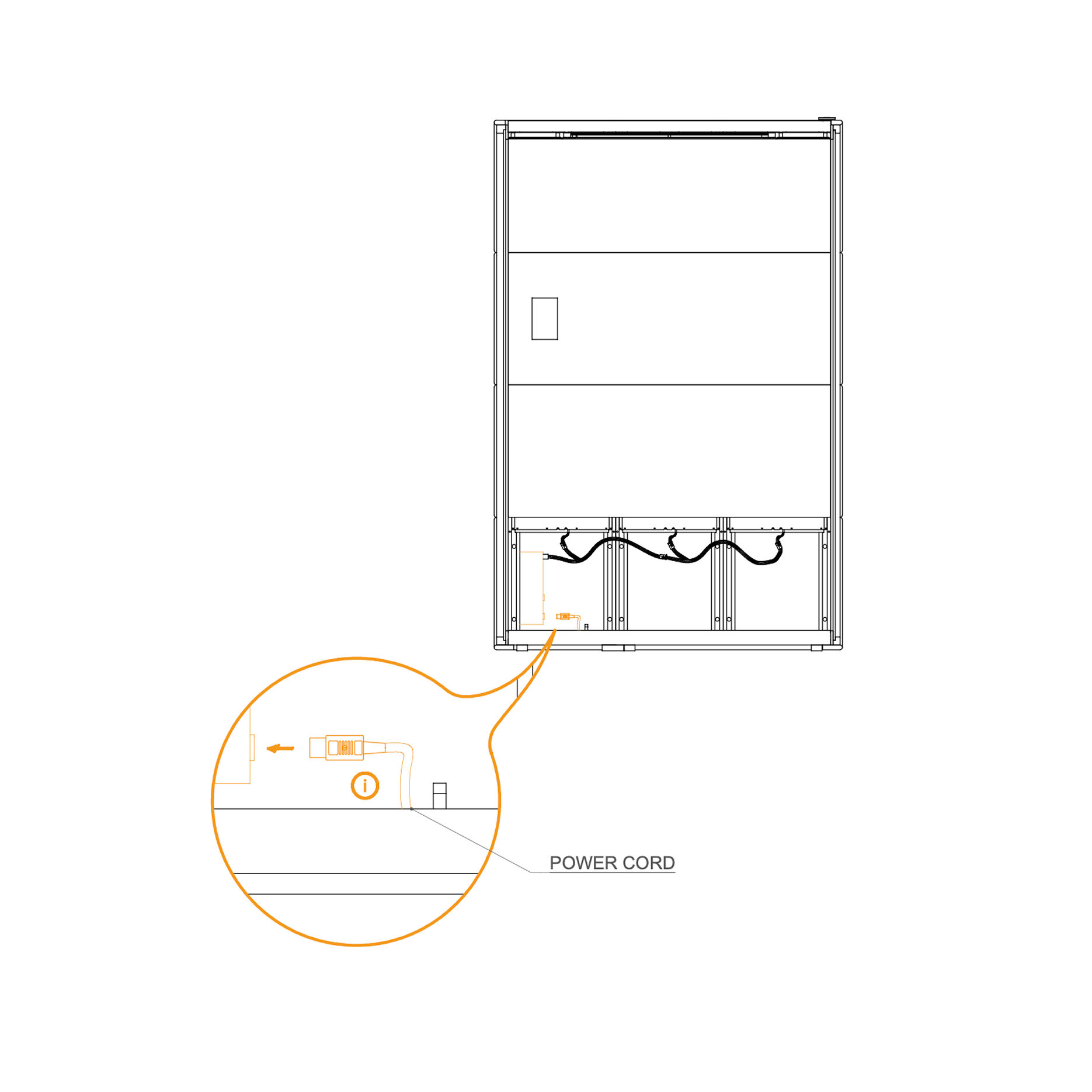
47. Connect the Power Supply Cord to Powerbox
Plug the power cord into the powerbox as shown in the detail view.
Ensure the connection is secure.
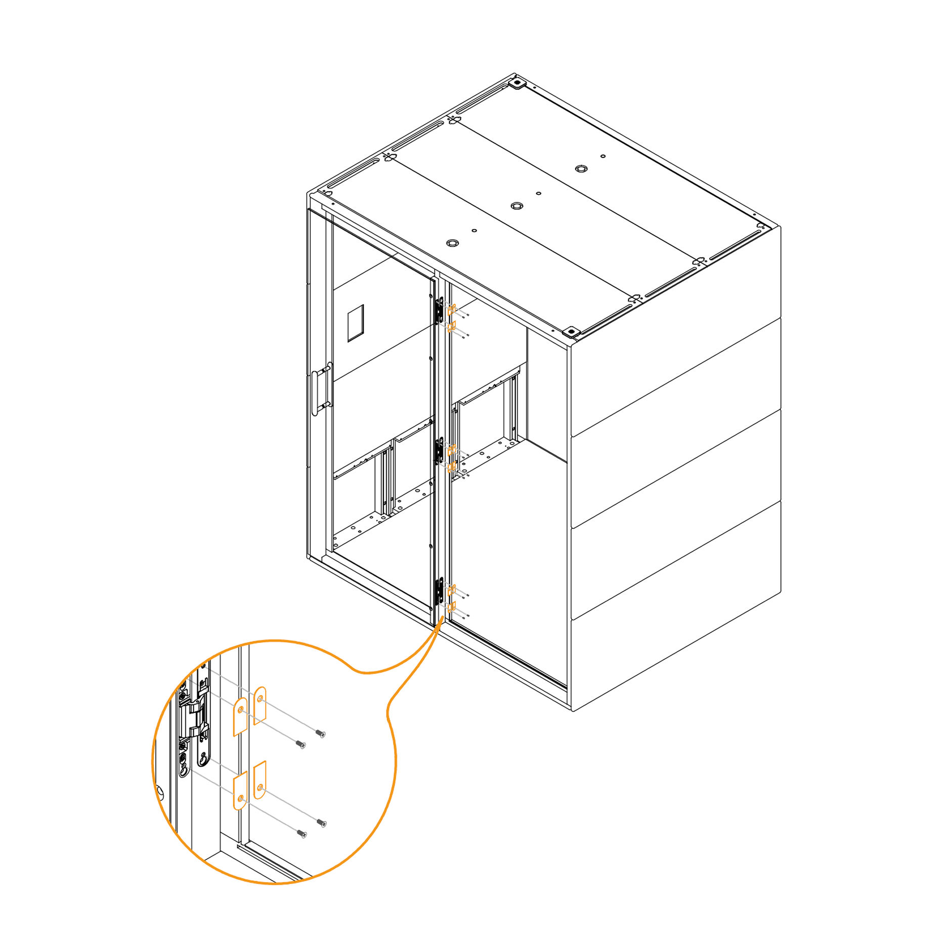
48. Install the Revision Door
Position the cord cover (K0487) over the power cord and secure it in place.
Parts used:
Cord cover | K0487 | 1×
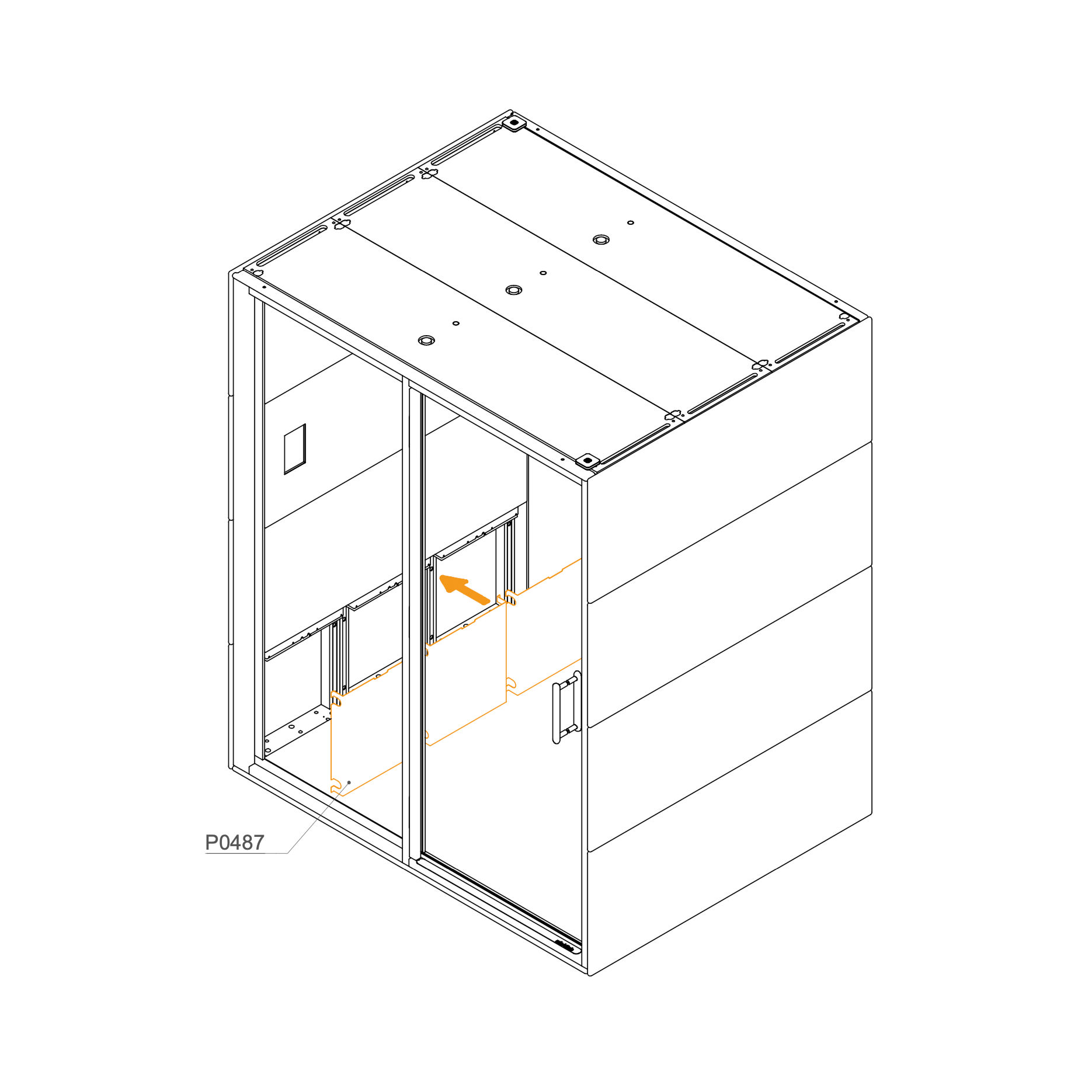
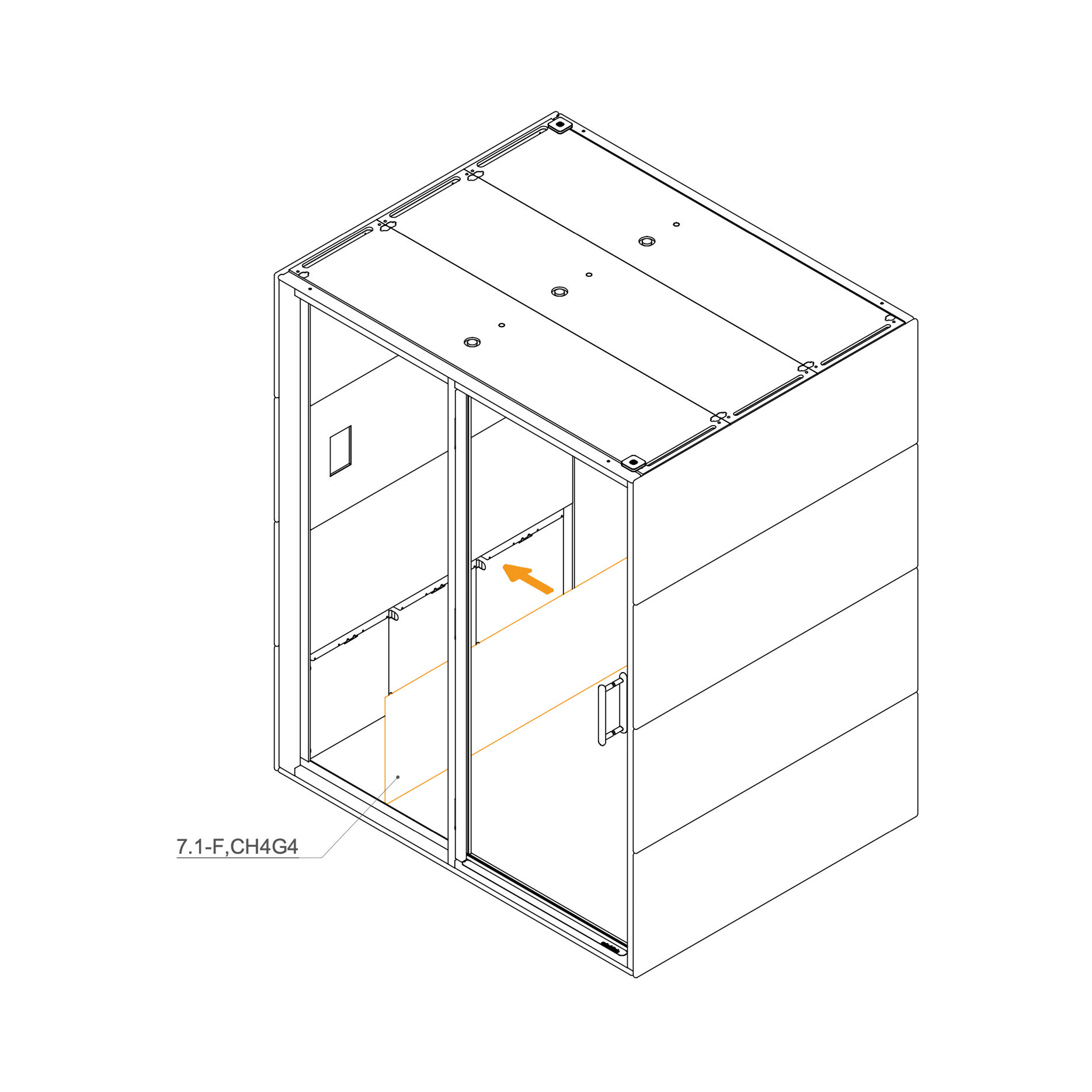
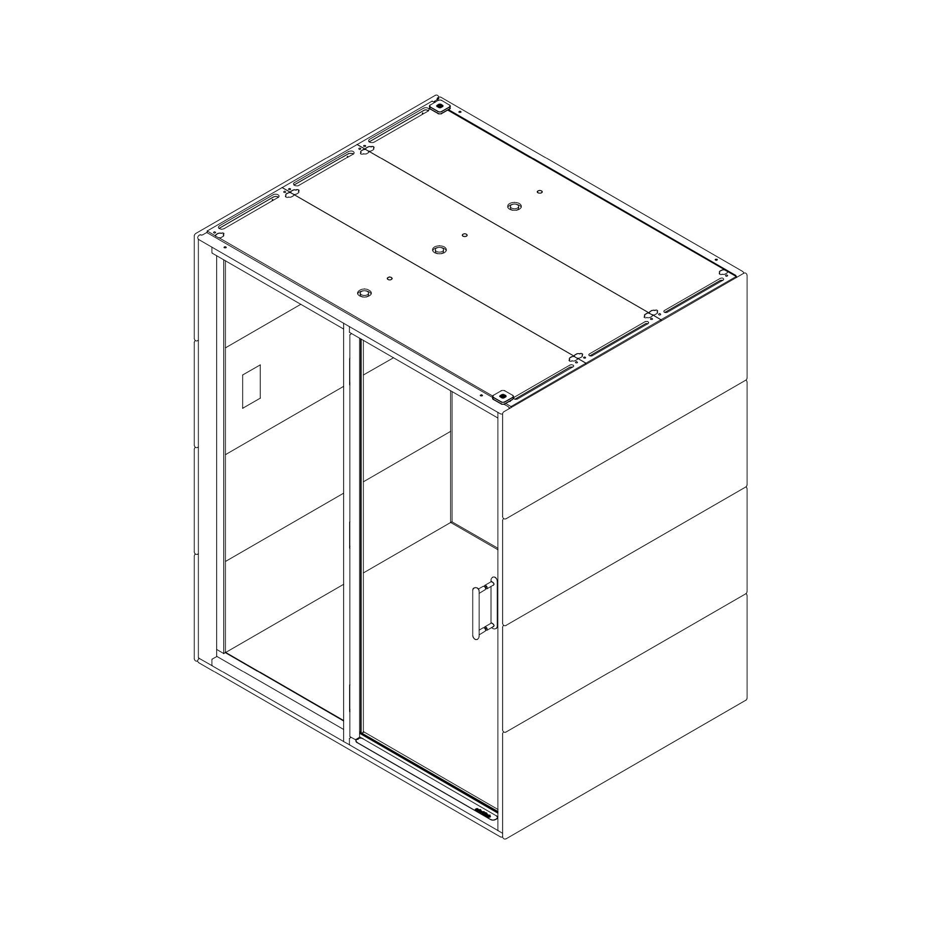
49. Final Checklist
Place the internal panel 7.1-F,CHG4 over the power cord section and secure in position.
Parts used:
interior panel | 7.1-F,CH4G4 | 1×
Initial Setup
50. Initial Setup
Following assembly, authorized personnel must perform a mandatory initial setup for all GEN4 products. This involves accessing the display settings to configure key parameters, such as the pod model, language, and time synchronization, to ensure all components function correctly.